Abstract
Free tissue transfer is the gold standard of reconstructive surgery to repair complex defects not amenable to local options or those requiring composite tissue. Ischemia reperfusion injury (IRI) is a known cause of partial free flap failure and has no effective treatment. Establishing a laboratory model of this injury can prove costly both financially as larger mammals are conventionally used and in the expertise required by the technical difficulty of these procedures typically requires employing an experienced microsurgeon. This publication and video demonstrate the effective use of a model of IRI in rats which does not require microsurgical expertise. This procedure is an in situ model of a transverse abdominis myocutaneous (TRAM) flap where atraumatic clamps are utilized to reproduce the ischemia-reperfusion injury associated with this surgery. A laser Doppler Imaging (LDI) scanner is employed to assess flap perfusion and the image processing software, Image J to assess percentage area skin survival as a primary outcome measure of injury.
Keywords: Medicine, Issue 76, Biomedical Engineering, Immunology, Anatomy, Physiology, Cellular Biology, Hematology, Surgery, Microsurgery, Reconstructive Surgical Procedures, Surgical Procedures, Operative, Myocutaneous flap, preconditioning, ischemia reperfusion injury, rat, animal model
Introduction
The goal of this protocol is to demonstrate a reliable and reproducible model of the ischemia-reperfusion injury observed in free tissue transfer to enable interventional strategies to be investigated.
Free tissue transfer is defined as the vascular detachment of an isolated block of tissue followed by autologous transplant of that tissue with anastomosis of the flap's transected vessels to native vessels at the recipient site. The procedure is known as FTT and the tissue being transferred referred to as the free flap.
Free tissue transfer is the gold standard approach for the correction of complex, composite defects where local options are unsuitable or unavailable.1-4 Ischemia reperfusion injury (IRI) is inevitable in free tissue transfer, contributes to flap failure5,6 and has no effective treatment. The elective nature of free flap surgeries permits administration of pharmacological agents to precondition against IRI.
IRI results in impaired flow through the microcirculation by endothelial activation and metabolic dysfunction,7 increased capillary permeability and subsequent interstitial edema7, influx of inflammatory cells,8 release of inflammatory mediators, reactive oxygen species9 and complement deposition.10 This complex process of hypoxia and subsequent reperfusion injury ultimately leads to cell death. A model of myocutaneous IRI enables the effectiveness of preconditioning strategies on clinical outcomes to be assessed. Recent work has validated the use of animal models of IRI studies as a surrogate for human IRI by comparing the molecular changes observed in human subjects and existing animal data.10,11
The rat transverse rectus abdominis myocutaneous (TRAM) flap was first described in 1987 in German12 and in 199313 in English. This model gained wide popularity13-25 as a cheap, robust model to investigate different strategies to reduce IRI associated with free tissue transfer.14,17-22 The majority of these studies were designed as unipedicled TRAM flaps based on the deep, inferior, epigastric vascular pedicle.15-18,20-22 Comparison of the data from these studies is complicated by the use of different sized cutaneous islands (10.5 - 30 cm2) and different lengths of postoperative follow-up (2 - 10 days). The average total percentage area flap necrosis in the control arm of these studies is 69 ± 6.2% (mean ± SEM). It should be noted that these six papers all employ the rectus abdominis muscle as a carrier for the vascular pedicle but do not expose, divide and microanastomose or clamp the vessels. Zhang et al.23 have described a true, free rat TRAM flap based on the superior epigastric vessels in which the flaps were raised, vessels divided and the myocutaneous flap transferred and microanastomosed to the groin vessels. This difficult technique required the microanastomosis of 0.45 - 0.5 mm caliber vessels. Only fifteen were performed and of these 67% survived.23 The model described by Zhang et al.23 is an excellent model for the human free TRAM flap as it truly mirrors the injury incurred during FTT. The other published models of a rat TRAM flap more accurately reflect the injuries incurred during a human pedicled TRAM but do not accurately reflect the IRI as these flap in do not undergo an ischemic period followed by reperfusion as the vascular pedicle is never clamped or divided and microanastomosis performed. This protocol and video describe a new model of free tissue transfer using the rat TRAM in which the IRI is replicated using microclamps. This more faithfully replicates IRI than the pedicle TRAM predecessors but is technically easier than performing the microanastomosis. Microclamps have been widely employed by transplant researchers to recreate IRI associated with solid organ transplant;26-33however, this is the first time it has been described in the rat TRAM flap.
Protocol
All surgery is performed in accordance with guidelines set out by the United Kingdom's Home Office and the University of Edinburgh's Veterinary Services Department.
1. Surgical Procedure Set-up Notes
Change into clean surgical scrubs, gown, scrub cap and mask. Clean all surfaces of the operating room including equipment with 2% chlorhexidine in 70% isopropyl alcohol.
Prior to surgery, autoclave all surgical supplies and instruments that will be used in the procedure. Sterile packs per operation should include: 3 drapes, gauze, cotton tip applicators, silicone sheeting and the surgical instruments, see the Table of Specific Surgical Materials and Tools and Figure 1. Weigh the rat and measure out the appropriate volume of buprenorphine (0.04 mg/kg) to be administered subcutaneously 1 hr before completing the procedure. Lay out; 3 x 1 ml syringes for subcutaneous fluid administration during surgery, 2 x 6-0 Vicryl sutures, 1 x 5-0 Ethilon sutures, a sterile marker with ruler and a 10-blade disposable scalpel, 4 - 5 pairs of sterile gloves and a hand-held cautery unit.
Place 4 x 10 ml sterile, 0.9% saline vials in a water bath warmed to 37 °C. This will be used for subcutaneous fluid replacement (1 ml/kg/hr) and to rinse the surgical site. Set up the homeothermic blanket, rectal probe, heat lamp, operating microscope and anesthetic rig. Turn on the laser and its software, set-up another anesthetic rig and place a heat pad underneath the black mat on which the animal will lay during the scan.
Use male, Lewis rats weighing 250-300 g. House rats for 7 days with food and water ad libitum with 12 hr light-dark cycles before any surgery is performed.
2. Anesthesia and Skin Preparation
Place the rat in the anesthetic rig's induction chamber and administer 4% isoflurane with 1L/min O2 for 2-3 min to induce anesthesia. Remove the anesthetized rat from the chamber and place it supine on the clean, heated mat. Maintain isoflurane at 1.5% using a nose cone. Apply lacrilube or similar agent to prevent corneal abrasion during the procedure. Perform a foot-pad pinch test to ensure the animal is adequately anesthetized before proceeding. Repeat this last test before each major step in the procedure and adjust the inhalational anesthetic concentration accordingly.
Closely shave the anterior abdominal using an electric shaver so that the entire abdominal surface is exposed. Apply depilating cream for the duration recommended by the supplier. Remove the cream and thoroughly rinse the skin with warmed sterile saline to remove all traces of the cream. Apply 2% chlorhexidine in 70% isopropyl alcohol to the skin and allow to dry before proceeding. This is the standard skin preparation in our unit based on current evidence for surgical site infection.34 Please discuss with your Veterinary Department what is standard procedure in your unit before electing a skin preparation protocol.
Place 2 drapes either side of the rat and take care to keep them sterile. Put on sterile gloves and with the aid of an assistant open up the sterile packs. Place all the instruments on one drape and the sutures, gauze, cotton applicators, silicone sheeting and sterile marker pen with ruler on the other.
Identify the midline using xiphisternum and the tail as reference points. Mark the midline. Measure 0.8 cm below the xiphisternum and mark this point. Draw a line perpendicular to the midline from this point. Taking the midline as the center of the flap mark out 1 cm and 2 cm to the left and the right of the midline. Draw vertical lines parallel to the midline from the points. Measure 4 cm below the original horizontal line and draw another parallel to it. Following these instructions a 4 x 4 cm flap divided into 4 equal strips is delineated (see Figure 2).
3. Laser Doppler Imaging
Carefully move the rat to the nose cone of the second anesthetic rig at the LDI scanner. Continue anesthesia at 1.5% isoflurane, 1L/min O2. Turn on the laser and follow the manufacturer's instructions to start scanning. After saving the scanned file return the rat back to the first rig and re-insert the rectal probe of the homeothermic blanket using soft white paraffin as a lubricant.
4. In situ TRAM flap - Myocutaneous Model of IRI
Re-scrub hands and put on fresh sterile gloves. Cut out a 5 cm diameter circle in the center of the remaining sterile drape and place this over the exposed abdomen to create a draped sterile-field.
Make an incision down the left lateral marked edge (Figure 3A and B). Achieve hemostasis. Make similar incisions down the horizontal lines to the left of the midline. Achieve hemostasis.
The fat overlying the left inferior rectus sheath should be visible. Using forceps and fine iris scissors carefully get underneath this fat. Take care not to damage the perforators coming through the left, anterior rectus sheath. The plane opened up by such dissection is that immediately above the anterior abdominal wall fascia. Continue dissecting in this plane around the demarcated margins. In the left iliac fossa lies the large, superficial circumflex iliac vessels- these can be tied or cauterized. Then extend the dissection medially with caution and only as far as the lateral margin of the left rectus muscle. There is an obvious color change at this point from pink to near white (Figure 3C). Carefully irrigate the area with sterile saline and check that hemostasis has been achieved before placing moist gauze over the area.
Repeat the procedure on the contralateral side but this time extend to the linea alba (mid line). Take care to identify and cauterize all the musculocutaneous perforators arising in the center of the right rectus abdominis muscle (Figure 3D). If this is not done properly it can result in a postoperative hematoma and spurious results. Similarly achieve hemostasis, irrigate and place moist gauze over the raised flap.
Return to the inferior margin of the left anterior rectus (Figure 3E and F). Cauterize the most inferior perforator seen. Proceed to cut a small (approx. 0.6 cm x 0.6 cm) window in the anterior rectus sheath using microscissors and pointed curved Graeffe forceps. Blunt dissect slowly down the lateral margin of the muscle until the muscle thins out but before the posterior sheath is breached. Then rotate the forceps and blunt dissect medially until the belly of the muscle is atop the curved edge of the forceps and the tips are free at the medial margin. Feed approximately 6 cm of 5-0 Ethilon into the jaws of the forceps and tie off the inferior rectus sheath. Upon completion of this step the myocutaneous flap is isolated on one dominant vessel- the deep superior epigastric vessels. Cover with a moist gauze.
Cut the silicone sheeting into ovals with smooth corners, (Figure 3G). These should be large enough to cover most of the area exposed under the fasciocutaneous portions of the flap. However, caution must be taken to ensure that the skin edge can be closed without any tension and the medial curve of the oval may have to be paired back to prevent it impairing flow through the remaining perforators. These are then sutured in place with 6-0 Vicryl (Figure 3H). Cover with moist gauze.
Using simple interrupted 5-0 Ethilon sutures 'peg out' the flap to reduce heat and water loss (Figure 3I). Cover with a moist gauze.
Extend the wound superiorly to the left of the xiphisternum (Figure 3I). Suture this to the upper left quadrant to improve the field-of-view.
Cut away any overlying fat to reveal the superior, left, anterior rectus sheath. Cut a small (0.6 cm x 0.6 cm) window in this sheath (Figure 3J). Extend the wound medially until a change in muscle fiber trajectory from vertical to oblique and consistency from tightly packed to loose fibrils is seen.
Insert the curved forceps carefully between these two muscles and open up a plane by blunt dissection. Carefully cut down only as far as the superior surface of these curved forceps cutting through the belly of the left rectus abdominis muscle to reveal the underlying deep, superior epigastric artery and vein (Figure 3K).
Using micro-instruments and high power on the operating microscope, carefully separate the artery and vein and strip off any surrounding fat.
Apply atraumatic Acland clamps to the artery and vein (B-1, "V" type) and start the timer to count down the 30 min ischemic period. Irrigate the clamped pedicle and cover with gauze. We did not employ vessel dilators such as verapamil or pabavarine but should vessel spasm be a problem, these drugs should be considered.
Administer the buprenorphine (0.04 mg/kg) and warmed, sterile saline (1 ml/kg/hr).
Starting at the top left corner, suture the flap in place with 6-0 Vicryl subcuticular sutures stopping and tying off at the xiphisternum.
When the 30 min ischemic time is over, carefully remove the clamps and irrigate the pedicle with warmed saline. Check that flow has been re-established. Please note that this ischaemic time was stipulated by the UK Home Office authority. Researchers working in other authorities may be able to extend this time. Extending the ischemic time will likely lead to worse clinical outcome.
Suture the cut edges of the rectus back in place with 6-0 Vicryl. Take care not to apply too much tension as this can lead to kinking of the vessels.
Complete the subcutaneous suturing taking care to bury all knots below the skin (Figure 3K).
Clean the wound area and allow it to dry. Re-draw the zones on the flap.
Re-scan the animal to obtain a postoperative image.
Re-apply lacrilube to the animal's eyes and place in a warmed incubator (37 °C) for 1 hr to recover before returning to the husbandry unit.
Critical steps within the protocol
The crux of the procedure is in identifying the deep, superior epigastric vessels. This is shown clearly in the accompanying film. In brief, a window is cut in the anterior rectus sheath to expose the underlying muscle fibers which will be running longitudinally. By extending the superficial dissection of the anterior rectus sheath medially a change in muscle fiber trajectory is observed from longitudinal to oblique. Insert blunt ended, curved, Graeffe forceps (or similar) at the intersection of these two bundles of muscle fibers. Blunt dissect laterally. Cut down, using micro scissors, onto the upper surface of the curved forceps held in this plane between the muscle fiber bundles. On removal of the Graeffe forceps the deep, superior epigastric artery and vein will be observed at the midpoint of the rectus abdominis muscle body. Strip off the fat overlying the vessels using micro instruments and apply the clamps.
The fasciocutaneous portions of the rat TRAM flap are thin enough to permit the flap to take as a full thickness skin graft. To prevent this and to ensure that this is a true model of IRI a thin, flexible silicon sheet is placed underneath the fasciocutaneous portions of the flap.35 This step has been adopted by other researchers undertaking rat TRAM models.17,21,25
Rats chew through knots so make sure all sutures are subcuticular and all knots are buried. In carrying out meticulous suturing autocannabilism of flaps as reported by other researchers can be avoided. 24
Following administration of Buprenorphine reduce maintenance anesthesia to 1% Isoflurane (1L/min O2).
Representative Results
Rat models are more economical than larger animals models,36 are disease-resistant in nature and may be genetically manipulated. Loose skinned animals, such as rodents, were thought to have a different arrangement of cutaneous blood supply compared to fixed skinned animals such as humans and pigs. In loose skinned animals, skin is supplied primarily by direct cutaneous blood vessels passing through the subcutaneous fat to the overlying skin (Figure 4) By contrast, fixed skinned animals derive cutaneous blood supply through vessels that course through the underlying muscles to supply the overlying integument via musculocutaneous perforators (Figure 4). Consequently there were concerns whether loose-skinned animals could be used in flap research. However, Taylor's work on angiosomes showed that there were discreet areas of rat skin that are supplied in an analogous manner as humans via musculocutaneous perforators. The anterior abdominal wall on which the transverse rectus myocutaneous (TRAM) flap is based is one such area.37,36,15
Relevant anatomy
The superior, deep, epigastric vessels are the dominant vascular pedicle in rats and six to ten perforators pass through the anterior rectus sheath to supply the overlying integument.13,15 The superior deep epigastric vessels in the rat enter the rectus abdominis muscle at the level of the xiphoid and continue, diminishing in caliber, toward the pubis. The lateral margins of the anterior abdomen are supplied by the superficial inferior and superior epigastric and circumflex iliac vessels.37 There is physiological overlap between the territories supplied by these direct cutaneous branches and those areas of integument supplied by musculocutaneous perforators via choke vessels.38 This is consistent with the anatomical and physiological vascular territories described in the human, though in the human the dominant vascular pedicle is the inferior rather than the superior epigastric artery.39
Transverse rectus abdominis myocutaneous (TRAM) flap
The transverse rectus abdominis flap was first described for reconstruction following radical resection of breast cancer in 1974.40 This myocutaneous flap is based on deep epigastric blood vessels and incorporates a portion of the rectus abdominis muscles and overlying integument. Throughout this article the TRAM flap will be divided into four equal areas called zones. They are numbered I-IV as per Schlefen et al. such that: Zone I (ZI) is the integument overlying the rectus abdominis muscle directly supplied by the vascular pedicle; Zone II (ZII) describes the integument overlying the contralateral rectus abdominis; Zone III (ZIII) the area lateral to Zone I; and Zone IV (ZIV) the area lateral to Zone II (see Figure 5).41
Laser Doppler imaging- assessing blood perfusion
Laser Doppler imaging provides a non-invasive means of assessing blood flow in the flap.42-45 A monochromatic light source is emitted from the laser head. This incident light (blue in Figure 6) is shifted by erythrocytes within the tissue. The degree of shift is related to the velocity of the erythrocytes. The shifted light (green in Figure 6) is detected by the photo detector within the scanner head and converted into a measurement of perfusion. These are given in arbitrary units, perfusion units (PU), and the data converted into an image much like a weather map wherein perfusion is graded from high to low and each value assigned a color (Figure 7). The color map generated illustrates relative perfusion between the different areas of the flap. Each instrument is carefully calibrated such that comparisons can be a made between subjects when the same scanner is employed
Rats underwent laser Doppler perfusion imaging using a Moor LD12 (Moor Instruments, Essex, UK) scanner pre-operatively, immediately postoperatively and at 24 and 48 hr after surgery.
Using the software provided with the LDI scanner a region of interest (R.O.I) can be superimposed onto the LDI image and the average perfusion of that area calculated (Figure 7).
Image J analysis of percentage area necrosis- primary outcome measure
Image J is an open-access image processing program courtesy of the National Institutes of Health.46 This can be used to measure areas and subsequently calculate the percentage skin area of each zone that is normal or fully necrosed at each time point (Figure 8).
Assessment of injury
The highest rates of skin necrosis were found in zone IV (see representative data in Figures 9 and 10) consistent with other studies.16,22,24,25,47 These findings correspond with the pattern of necrosis reported clinically in human TRAM flaps confirming that this is a faithful representation of the clinical problem.14 The total percentage area flap necrosis was 37.86 ± 5.4% (mean ± SEM).
Changes in skin blood
LDI perfusion scanning was employed to assess blood flow in the TRAM flap model. This is a simple, non-invasive and reproducible means of assessing perfusion (Figures 9 and 11). Perfusion decreased to 58.4 ± 0.49% (n = 10, mean ± SEM) immediately postoperatively, 56.98 ± 0.41% at 24 hr and 92.4 ± 0.6% compared to the pre-operative values for the whole flap. The areas of the flap with lowest perfusion in the immediate postoperative and 24 hr scans indicate areas where necrosis will subsequently develop at 48 hr (see Figure 9).
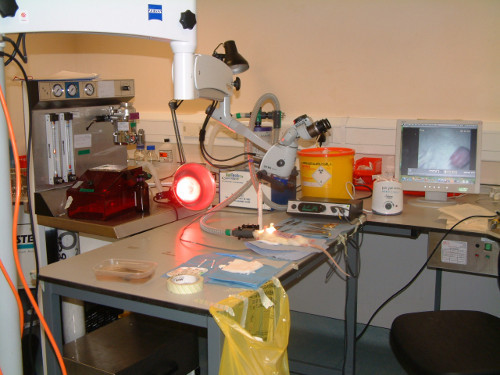 Figure 1. Equipment set-up. The anesthetic rig with red induction chamber are seen behind desk. The rat is lying supine with anesthesia maintained via a nose cone. A heat lamp is employed to increase ambient temperature. Above the rat is the operating microscope. To the left of the rat is a sterile drape with gauze, sutures etc. To the right of the rat is a sterile drape with the surgical instruments. Core temperature is maintained using a homeothermic blanket (underneath the rat) and rectal probe attached to the Harvard apparatus device (black box in front of the sharps bin).
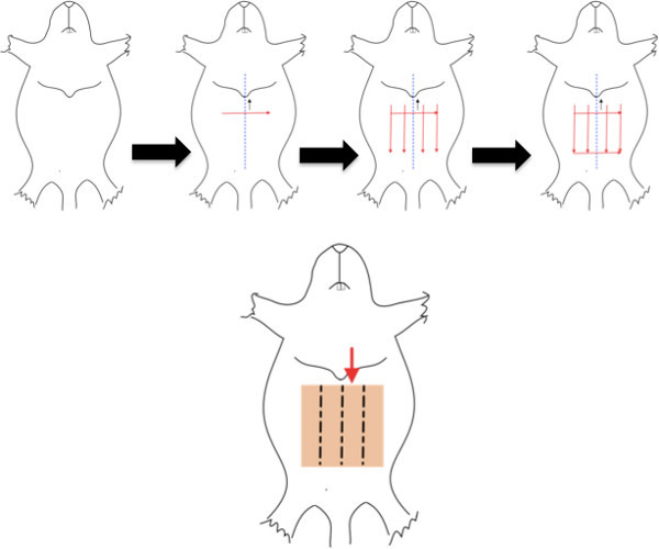 Figure 2. Marking out the flap boundaries and zones. The depilated rat is placed supine. The midline is identified and marked (blue dashed line). A line is marked perpendicular to the midline 0.8 cm below the xiphisternum. 4 lines are drawn parallel to the midline, 1 cm apart. A last line is drawn parallel and 4 cm below the second line to complete the square. Click here to view larger figure.
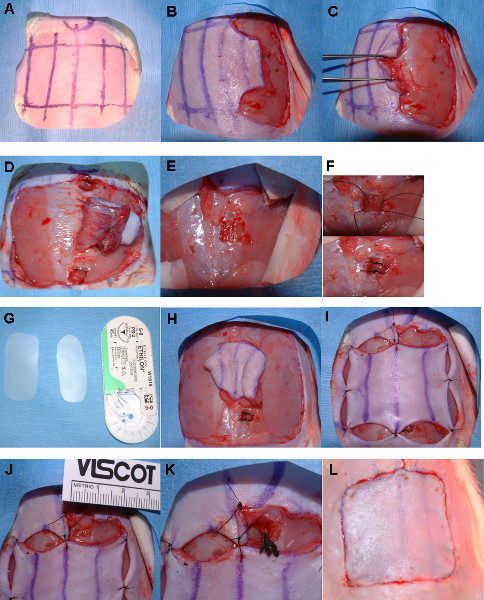 Figure 3. Step-by-step surgical approach. The flap is delineated as previously described (3A). The left lateral margin is incised (3B) and dissection continued medially in the plane immediately superficial to the anterior abdominal wall fascia to the lateral margin of the left rectus (3C). The same steps are conducted on the contralateral side but the dissection continued medially to the linea alba (midline), (3D). Cauterize the musculocutaneous perforators arising from the center of the right rectus abdominis muscle. A small window is cut in the inferior aspect of left rectus sheath (3E) and the inferior rectus tied off (3F). Silicone sheeting is then cut and sutured in place underneath the fasciocutaneous portions of the flap (3G
H). The flap is then 'pegged' out (3-I). Steps (3G and I) can be performed before or after steps (3E and F). A small window is cut in the superior aspect of the left, anterior rectus sheath (3-J). The exposed muscle is then carefully examined. A change in muscle fiber trajectory from parallel to oblique and tightly packed to loosely packed fibrils will be seen medially. Pass the curved Graeffe forceps between these muscle planes and blunt dissect laterally. Cut down onto the closed, upper surface of these forceps to expose the vascular pedicle. Remove surrounding fat and expose the vessels for clamping. Place Acland clamps on the artery and vein (3K) and count down the ischemic time period. Start subcuticular suturing leaving the area immediately above the clamps until last. Remove the clamps after the allotted period and appose the free ends of the left rectus abdominis muscle. Complete the subcuticular sutures (3L).
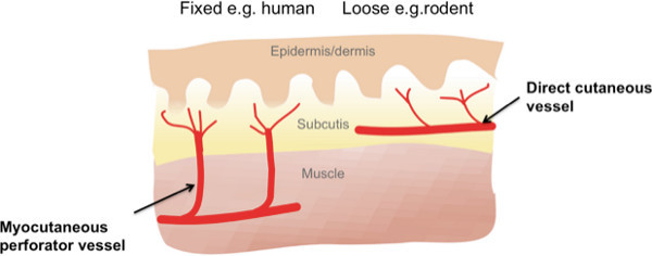 Figure 4. Cutaneous blood supply in fixed and loose skinned animals. Cutaneous blood supply in loose skinned mammals such as rats is predominantly via direct cutaneous branches rather than musculocutaneous perforators as in fixed skin mammals such as humans and pigs. For this reason rats have not historically been favored for plastic surgical research. This has been shown to be an out-dated notion and specific areas of the rat such as the anterior abdominal wall are supplied by musculocutaneous perforators and are therefore suitable areas to use for flap models. Click here to view larger figure.
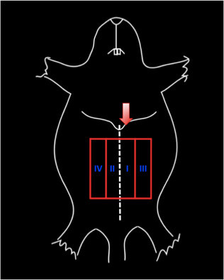 Figure 5. Zones of the transverse abdominis myocutaneous flap as described by Schlefen et al. in 1983. The red arrow indicates the vascular pedicle (in this case the left, superior, deep epigastric vessels). The blue roman numerals show the 4 zones numbered I-IV based on their position relative to the vascular pedicle such that: Zone I (ZI) is the integument overlying the rectus abdominis muscle directly supplied by the vascular pedicle; Zone II (ZII) describes the integument overlying the contralateral rectus abdominis; Zone III (ZIII) the area lateral to Zone I; and Zone IV (ZIV) lateral to zone II.
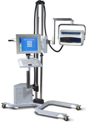 Figure 6. Laser Doppler imaging scanner. Moor LD12 scanner assesses perfusion by sending out a monochromatic light (blue arrows) sources which is shifted by the moving erythrocytes within the skin. The degree of shift is related to the velocity of the erythrocytes. This shifted light (green arrows) is detected by the photo-scanner and perfusion in that area calculated. A mirror then moves the beam in a sequential manner so that the whole anterior abdominal wall can be scanned in approximately 7 min.
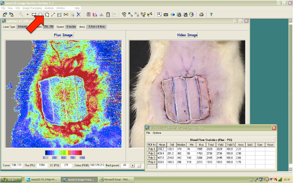 Figure 7. Assessing average perfusion using LDI software. Select the polygon icon from the tool bar (red arrow) then the region of interest (ROI) selection tool (rectangle with the blue cross, 2 icons to the right of the polygon tool). Using the mouse draw around the ROI, in this figure all 4 zones are marked. Before moving to the next ROI click on the rectangle with the blue square again. Once all the desired ROIs are selected press the stats icon in the center of the tool bar (the icon of a notepad with numbers on it) and the average perfusion statistics for each ROI will pop-up in a new window as shown.
Figure 8. Image J analysis.
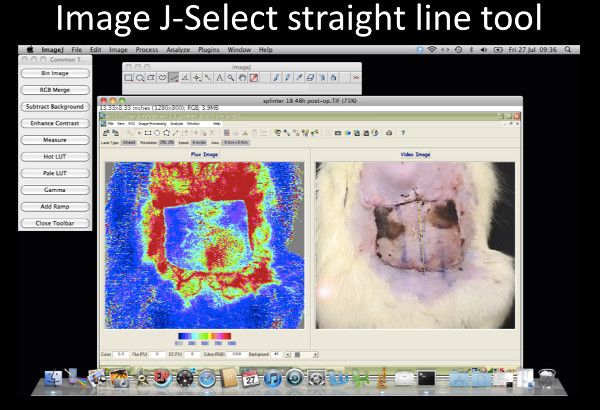 Figure 8-1. Image J- Select straight-line tool. Select the straight-line tool, draw a line down the center of the flap as shown. Click here to view larger figure.
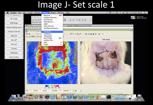 Figure 8-2. Image J- Set scale 1. Select Analyze from the tool bar and from the drop down menu select set scale.Click here to view larger figure.
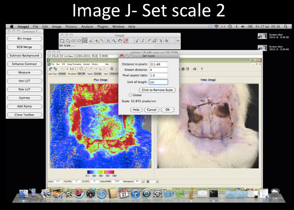 Figure 8-3. Image J- Set scale 2. On the pop up window set the scale to 4 cm. Click here to view larger figure.
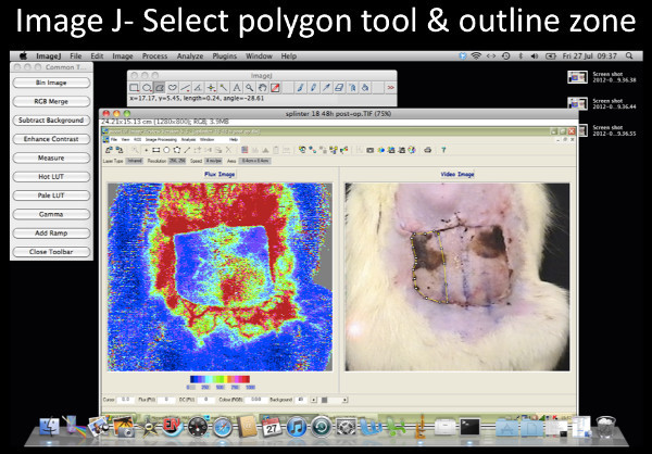 Figure 8-4. Image J- Select the polygon tool & outline zone of interest. Select polygon tool (highlighted icon) and outline the zone of interest. The total perimeter of zone IV is outlined in this example. Click here to view larger figure.
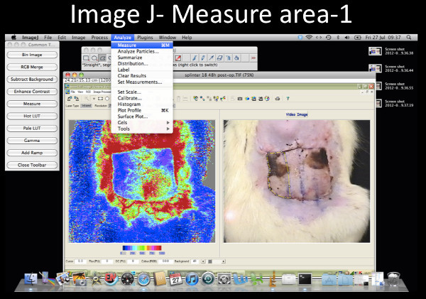 Figure 8-5. Image J- Measure area 1. Select Analyze from the tool bar and on the drop down menu select Measure. Click here to view larger figure.
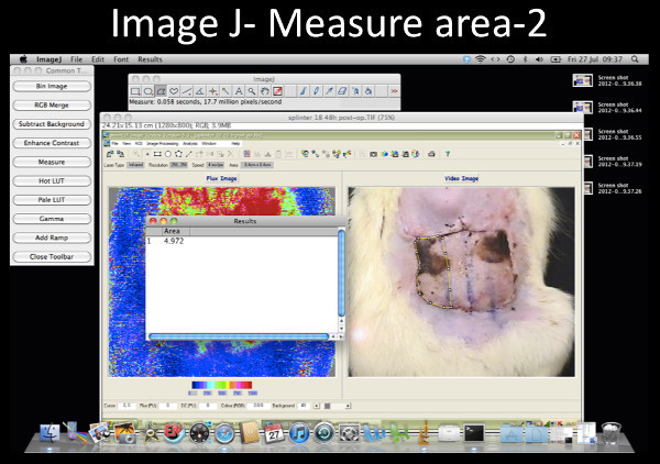 Figure 8-6. Image J- Measure area 2. The area will be displayed in a separate results window. Click here to view larger figure.
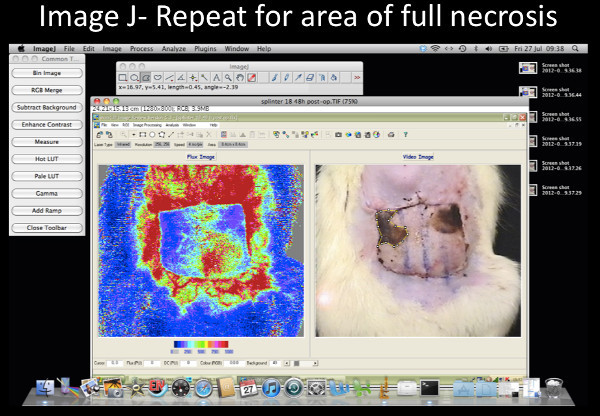 Figure 8-7. Image J- Repeat for area of full necrosis. Repeat the previous 2 steps but this time only outline the necrosed area. This example shows the full necrosis in zone IV outlined. To calculate the percentage area full necrosis divide the latter value by the former and multiply by 100.Click here to view larger figure.
 Figure 9. Montage of representative images of this procedure. Caption: Each row represents a different subject. Photographs (left) and corresponding LDI image (right) are shown at the 4 different time points (from left to right: pre-operatively, postoperatively, at 24 hr and at 48 hr after surgery). It is clear that necrosis occurs consistently in zones ZIV and III. The color scale on the bottom right shows the colors and their corresponding perfusion units. Red- high perfusion, blue- low perfusion). Click here to view larger figure.
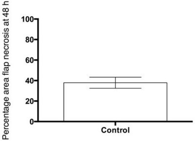 Figure 10. Representative results- skin necrosis expressed as a percentage of total flap area at 48 hr. Caption: Percentage area full necrosis of the flap assessed clinically and measured using image J software at 48 hr. The mean and SEM shown, n = 10.
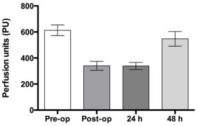 Figure 11. Representative results- Laser Doppler imaging. Caption: Laser Doppler imaging to show the average perfusion measured in perfusion units of the flap in control subjects pre-operatively, postoperatively, at 24 and 48 hr. The mean and SEM shown, n = 10.
Discussion
Modifications and trouble shooting
The protocol presented here reproduces the IRI seen in free tissue transfer in an experimental system enabling further understanding of that process and provides a means to investigate means of ameliorating IRI and improving outcome. This could easily be modified to produce a more severe injury if it were based on the non-dominant, deep, inferior epigastric pedicle or if the ischemic time were increased.
Limitations of technique
The anterior abdominal wall of the rat has significantly less subcutaneous fat than the anterior abdominal wall of most women undergoing TRAM flap surgery for breast reconstruction. The model outlined in this text is designed specifically as a model of ischemia reperfusion injury in myocutaneous flaps so that the effects of preconditioning therapies can be evaluated using skin necrosis and perfusion as outcome measures. The procedure detailed in this article does not specifically model problems such as fat necrosis which are incurred in human TRAM flaps when flaps with significant fat components are deliberately harvested to create projection for large breast reconstructions.
Direct in-vivo observation of the microcirculation is not demonstrated in this protocol but has been described in the cremaster muscle model48 and in an osteomyocutaneous flap.7,49-51 The TRAM model is a myocutaneous flap model, if researchers are particularly interested in osteomyocutaneous flaps this model is not appropriate but an alternative model has been described in the literature.50
Significance with respect to other methods
Most published rat TRAM models use the rectus abdominis muscle surrounding the chosen vascular pedicle as a carrier for the vascular pedicle.13-22,24,25 They do not accurately reflect the IRI as the flap is never undergoes a true period of ischemia followed by reperfusion. Therefore, compared to these papers the model detailed in this protocol gives reproducible, controlled myocutaneous IRI. Researchers have also performed this as a free flap to the groin vessels23 however this is technically extremely demanding as the deep superior, epigastric artery and vein measure 0.45 and 0.5 mm respectively. This protocol represents a simpler model.
Future applications
Research in improving outcome in free tissue transfer has focused primarily on preconditioning strategies. These strategies are employed or initiated before the surgery with the aim of 'training' the transferred tissue to withstand better the free tissue transfer surgery and this improve outcome. There are two main ways in which this can be achieved: pharmacological or ischemic preconditioning.52 A lot of this work has been performed on pigs which are more expensive to house and more difficult to work with than rats. The protocol described in this paper can be used to test these strategies in a laboratory animal which is easy to house and work with and in which there is possibility to work with genetically manipulated animals.
Disclosures
We have no disclosures.
Acknowledgments
This work was funded by the Medical Research Council grant G1000299.
The corresponding author would like to thank Gary Borthwick, University of Edinburgh, for assisting during the surgery.
The authors would like to acknowledge advice from Helen Douglas and Iain Mackay and allowing us to observe their Deep Inferior Epigastric (DIEP) flap procedure (Canniesburn Plastic Surgery Unit, Glasgow Royal Infirmary, 84 Castle Street, Glasgow G4 0SF, UK).
The authors would also like to thank Gary Blackie at the University of Edinburgh for his help in producing the video for this article.
References
- Wang X, et al. Free anterolateral thigh adipofascial flap for hemifacial atrophy. Ann. Plast. Surg. 2005;55(6):617–622. doi: 10.1097/01.sap.0000189659.76694.e2. [DOI] [PubMed] [Google Scholar]
- Eckardt A, Fokas K. Microsurgical reconstruction in the head and neck region: An 18-year experience with 500 consecutive cases. J. Cranio. Maxill. Surg. 2003;31(4):197–201. doi: 10.1016/s1010-5182(03)00039-8. [DOI] [PubMed] [Google Scholar]
- Yazar S, et al. Safety and reliability of microsurgical free tissue transfers in paediatric head and neck reconstruction - a report of 72 cases. J. Plast. Reconstr. Aes. 2008;61(7):767–771. doi: 10.1016/j.bjps.2007.10.022. [DOI] [PubMed] [Google Scholar]
- Blondeel PN, Landuyt KHV, Monstrey SJ. Surgical-technical aspects of the free diep flap for breast reconstruction. Operat. Tech. Plast. Reconstr. Surg. 1999;6(1):27–37. [Google Scholar]
- Siemonow M, Arslan E. Ischaemia/reperfusion injury: A review in relation to free tissue transfers. Microsurgery. 2004;24:468–475. doi: 10.1002/micr.20060. [DOI] [PubMed] [Google Scholar]
- Wang WZ. Investigation of reperfusion injury and ischaemic preconditioning in microsurgery. Microsurgery. 2009;29:72–79. doi: 10.1002/micr.20587. [DOI] [PMC free article] [PubMed] [Google Scholar]
- Rucker M, et al. Reduction of inflammatory response in composite flap transfer by local stress conditioning-induced heat-shock protein 32. Surgery. 2001;129(3):292–301. doi: 10.1067/msy.2001.111079. [DOI] [PubMed] [Google Scholar]
- Cetinkale O, et al. Involvement of neutrophils in ischemia-reperfusion injury of inguinal island skin flaps in rats. Plast. Reconstr. Surg. 1998;102(1):153–160. doi: 10.1097/00006534-199807000-00024. [DOI] [PubMed] [Google Scholar]
- Korthuis RJ, Granger DN, Townsley MI, Taylor AE. The role of oxygen-derived free radicals in ischemia-induced increases in canine skeletal muscle vascular permeability. Circ. Res. 1985;57(4):599–609. doi: 10.1161/01.res.57.4.599. [DOI] [PubMed] [Google Scholar]
- Eisenhardt SU, et al. Monitoring molecular changes induced by ischemia/reperfusion in human free muscle flap tissue samples. Ann. Plast. Surg. 2012;68(2):202–208. doi: 10.1097/SAP.0b013e3181f77ba5. [DOI] [PubMed] [Google Scholar]
- Dragu A, et al. Gene expression analysis of ischaemia and reperfusion in human microsurgical free muscle tissue transfer. J. Cell. Mol. Med. 2011;15(4):983–993. doi: 10.1111/j.1582-4934.2010.01061.x. [DOI] [PMC free article] [PubMed] [Google Scholar]
- Tilgner A, Herrberger U. [myocutaneous flap models in the rat. Anatomy, histology and preparation technic of the myocutaneous rectus abdominis flap] Z. Versuchstierkd. 1987;29(5-6):231–236. [PubMed] [Google Scholar]
- Dunn RM, Huff W, Mancoll J. The rat rectus abdominis myocutaneous flap: A true myocutaneous flap model. Ann. Plast. Surg. 1993;31(4):352–357. doi: 10.1097/00000637-199310000-00012. [DOI] [PubMed] [Google Scholar]
- Clugston PA, Perry LC, Fisher J, Maxwell GP. A rat transverse rectus abdominis musculocutaneous flap model: Effects of pharmacological manipulation. Ann. Plast. Surg. 1995;34(2):154–161. [PubMed] [Google Scholar]
- Ozgentas HE, Shenaq S, Spira M. Development of a tram flap model in the rat and study of vascular dominance. Plast. Reconstr. Surg. 1994;94(7):1012–1017. [PubMed] [Google Scholar]
- Doncatto LF, da Silva JB, da Silva VD, Martins PD. Cutaneous viability in a rat pedicled tram flap model. Plast. Reconstr. Surg. 2007;119(5):1425–1430. doi: 10.1097/01.prs.0000258534.46634.e7. [DOI] [PubMed] [Google Scholar]
- Lineaweaver WC, et al. Vascular endothelium growth factor, surgical delay, and skin flap survival. Ann. Surg. 2004;239(6):866–873. doi: 10.1097/01.sla.0000128682.53915.92. [DOI] [PMC free article] [PubMed] [Google Scholar]
- Rezende FC, et al. Electroporation of vascular endothelial growth factor gene in a unipedicle transverse rectus abdominis myocutaneous flap reduces necrosis. Ann. Plast. Surg. 2010;64(2):242–246. doi: 10.1097/SAP.0b013e318196cbe0. [DOI] [PubMed] [Google Scholar]
- Zacchigna S, et al. Improved survival of ischemic cutaneous and musculocutaneous flaps after vascular endothelial growth factor gene transfer using adeno-associated virus vectors. Am. J. Pathol. 2005;167(4):981–991. doi: 10.1016/S0002-9440(10)61188-1. [DOI] [PMC free article] [PubMed] [Google Scholar]
- Zhang F, et al. Improvement of skin paddle survival by application of vascular endothelial growth factor in a rat tram flap model. Ann. Plast. Surg. 2010;46:314–319. doi: 10.1097/00000637-200103000-00019. [DOI] [PubMed] [Google Scholar]
- Hijjawi J, et al. Platelet-derived growth factor β, but not fibroblast growth factor 2, plasmid DNA improves survival of ischemic myocutaneous flaps. Arch. Surg. 2004;139(2):142–147. doi: 10.1001/archsurg.139.2.142. [DOI] [PubMed] [Google Scholar]
- Wong MS, et al. Basic fibroblast growth factor expression following surgical delay of rat transverse rectus abdominis myocutaneous flaps. Plast. Reconstr. Surg. 2004;113(7):2030–2036. doi: 10.1097/01.prs.0000122217.16985.52. [DOI] [PubMed] [Google Scholar]
- Zhang F, et al. Microvascular transfer of the rectus abdominis muscle and myocutaneous flap in rats. Microsurgery. 1993;14(6):420–423. doi: 10.1002/micr.1920140614. [DOI] [PubMed] [Google Scholar]
- Hallock GG, Rice DC. Comparison of tram and diep flap physiology in a rat model. Plast Reconstr Surg. 2004;114(5):1179–1184. doi: 10.1097/01.prs.0000135856.70756.f2. [DOI] [PubMed] [Google Scholar]
- Qiao Q, et al. Patterns of flap loss related to arterial and venous insufficiency in the rat pedicled tram flap. Annals of Plastic Surgery. 1999;43(2):171. [PubMed] [Google Scholar]
- Persy VP, Verhulst A, Ysebaert DK, De Greef KE, De Broe ME. Reduced postischemic macrophage infiltration and interstitial fibrosis in osteopontin knockout mice. Kidney Int. 2003;63(2):543–553. doi: 10.1046/j.1523-1755.2003.00767.x. [DOI] [PubMed] [Google Scholar]
- Li Y, et al. Overexpression of cgmp-dependent protein kinase i (pkg-i) attenuates ischemia-reperfusion-induced kidney injury. Am. J. Physiol. Ren. Physiol. 2012;302(5):561–570. doi: 10.1152/ajprenal.00355.2011. [DOI] [PMC free article] [PubMed] [Google Scholar]
- Hunter JP, et al. Effects of hydrogen sulphide in an experimental model of renal ischaemia-reperfusion injury. Brit. J. Surg. 2012;99(12):1665–1671. doi: 10.1002/bjs.8956. [DOI] [PubMed] [Google Scholar]
- Hamada T, Fondevila C, Busuttil RW, Coito AJ. Metalloproteinase-9 deficiency protects against hepatic ischemia/reperfusion injury. Hepatology. 2008;47(1):186–198. doi: 10.1002/hep.21922. [DOI] [PubMed] [Google Scholar]
- Duarte S, Hamada T, Kuriyama N, Busuttil RW, Coito AJ. Timp-1 deficiency leads to lethal partial hepatic ischemia and reperfusion injury. Hepatology. 2012;56(3):1074–1085. doi: 10.1002/hep.25710. [DOI] [PMC free article] [PubMed] [Google Scholar]
- Shen XD, et al. Cd154-cd40 t-cell costimulation pathway is required in the mechanism of hepatic ischemia/reperfusion injury, and its blockade facilitates and depends on heme oxygenase-1 mediated cytoprotection. Transplantation. 2002;74(3):315–319. doi: 10.1097/00007890-200208150-00005. [DOI] [PubMed] [Google Scholar]
- Liu J, et al. Endoplasmic reticulum stress modulates liver inflammatory immune response in the pathogenesis of liver ischemia and reperfusion injury. Transplantation. 2012;94(3):211–217. doi: 10.1097/TP.0b013e318259d38e. [DOI] [PMC free article] [PubMed] [Google Scholar]
- Pan GZ, et al. Bone marrow mesenchymal stem cells ameliorate hepatic ischemia/reperfusion injuries via inactivation of the mek/erk signaling pathway in rats. J. Surg. Res. 2012;178(2):935–948. doi: 10.1016/j.jss.2012.04.070. [DOI] [PubMed] [Google Scholar]
- Darouiche RO, et al. Chlorhexidine-alcohol versus povidone-iodine for surgical-site antisepsis. New. Engl. J. Med. 2010;362(1):18–26. doi: 10.1056/NEJMoa0810988. [DOI] [PubMed] [Google Scholar]
- Fukui A, Inada Y, Murata K, Tamai S. Plasmatic imbibition" in the rabbit flow-through venus flap, using horseradish peroxidase and fluoroscein. J. Reconstr. Mirosurg. 1995;11:255–264. doi: 10.1055/s-2007-1006541. [DOI] [PubMed] [Google Scholar]
- Dunn RM, Mancoll J. Flap models in the rat: A review and and reappraisal. Plast. Reconstr. Surg. 1992;90(2):319–328. [PubMed] [Google Scholar]
- Taylor G, Minabe T. The angiosomes of the mammals and other vertebrates. Plast. Reconstr. Surg. 1992;89(2):181–215. doi: 10.1097/00006534-199202000-00001. [DOI] [PubMed] [Google Scholar]
- Taylor G, Corlett R, Boyd J. The versatile deep inferior epigastric (inferior rectus abdominis) flap. Brit. J. Plast. Surg. 1984;37(3):330–350. doi: 10.1016/0007-1226(84)90076-6. [DOI] [PubMed] [Google Scholar]
- Taylor G, Corlett R, Boyd J. The extended deep inferior epigastric flap: A clinical technique. Plast. Reconstr. Surg. 1983;72(6):751–765. doi: 10.1097/00006534-198312000-00001. [DOI] [PubMed] [Google Scholar]
- Tai Y, Hasegawa H. A tranverse abdominal flap for reconstruction after radical operations for recurrent breast cancer. Plast. Reconstr. Surg. 1974;53(1):52–54. doi: 10.1097/00006534-197401000-00009. [DOI] [PubMed] [Google Scholar]
- Scheflan M, Dinner MI. The transverse abdominal island flap: Part i. Indications, contraindications, results, and complications. Ann. Plast. Surg. 1983;10:24–35. doi: 10.1097/00000637-198301000-00005. [DOI] [PubMed] [Google Scholar]
- Tindholdt TT, Saidian S, Pripp AH, Tonseth KA. Monitoring microcirculatory changes in the deep inferior epigastric artery perforator flap with laser doppler perfusion imaging. Ann. Plast. Surg. 2011;67(2):139–142. doi: 10.1097/SAP.0b013e3181f3e39b. [DOI] [PubMed] [Google Scholar]
- Tindholdt TT, Saidian S, Tonseth KA. Microcirculatory evaluation of deep inferior epigastric artery perforator flaps with laser doppler perfusion imaging in breast reconstruction. J. Plast. Surg. Hand. Surg. 2011;45(3):143–147. doi: 10.3109/2000656X.2011.579721. [DOI] [PubMed] [Google Scholar]
- Booi DI, Debats IBJG, Boeckx WD, van der Hulsi RRWJ. A study of perfusion of the distal free-tram flap using laser doppler flowmetry. J. Plast. Reconstr. Aes. 2008;61:282–288. doi: 10.1016/j.bjps.2007.07.014. [DOI] [PubMed] [Google Scholar]
- Hallock GG. Physiological studies using laser doppler flowmetry to compare blood flow to the zones of the free tram flap. Ann. Plast .Surg. 2001;47(3):229–233. doi: 10.1097/00000637-200109000-00002. [DOI] [PubMed] [Google Scholar]
- Collin T. Image j for microscopy. Biotechniques. Suppl. 2007;43(1):25–30. doi: 10.2144/000112517. [DOI] [PubMed] [Google Scholar]
- Hallock G, Rice D. Physiologic superiority of the anatomic dominant pedicle of the tram flap in a rat model. Plast. Reconstr. Surg. 1995;96:111–118. doi: 10.1097/00006534-199507000-00017. [DOI] [PubMed] [Google Scholar]
- Ozmen S, Ayhan S, Demir Y, Siemionow M, Atabay K. Impact of gradual blood flow increase on ischaemia-reperfusion injury in the rat cremaster microcirculation model. J. Plast. Reconstr. Aes. 2008;61(8):939–948. doi: 10.1016/j.bjps.2007.05.017. [DOI] [PubMed] [Google Scholar]
- Rucker M, Vollmar B, Roesken F, Spitzer WJ, Menger MD. Microvascular transfer-related abrogation of capillary flow motion in critically reperfused composite flaps. Brit. J. Plast Surg. 2002;55(2):129–135. doi: 10.1054/bjps.2001.3748. [DOI] [PubMed] [Google Scholar]
- Rucker M, Kadirogullari B, Vollmar B, Spitzer WJ, Menger MD. Improvement of nutritive perfusion after free tissue transfer by local heat shock-priming-induced preservation of capillary flowmotion. J. Surg. Res. 2005;123:102–108. doi: 10.1016/j.jss.2004.07.012. [DOI] [PubMed] [Google Scholar]
- Rucker M, et al. New model for in vivo quantification of microvascular embolization, thrombus formation, and recanalization in composite flaps. J. Surg. Res. 2002;108(1):129–137. doi: 10.1006/jsre.2002.6531. [DOI] [PubMed] [Google Scholar]
- Wang WZ, Baynosa RC, Zamboni WA. Update on ischemia-reperfusion injury for the plastic surgeon. Plast. Reconstr. Surg. 2011;128(6):685e–692e. doi: 10.1097/PRS.0b013e318230c57b. [DOI] [PubMed] [Google Scholar]


