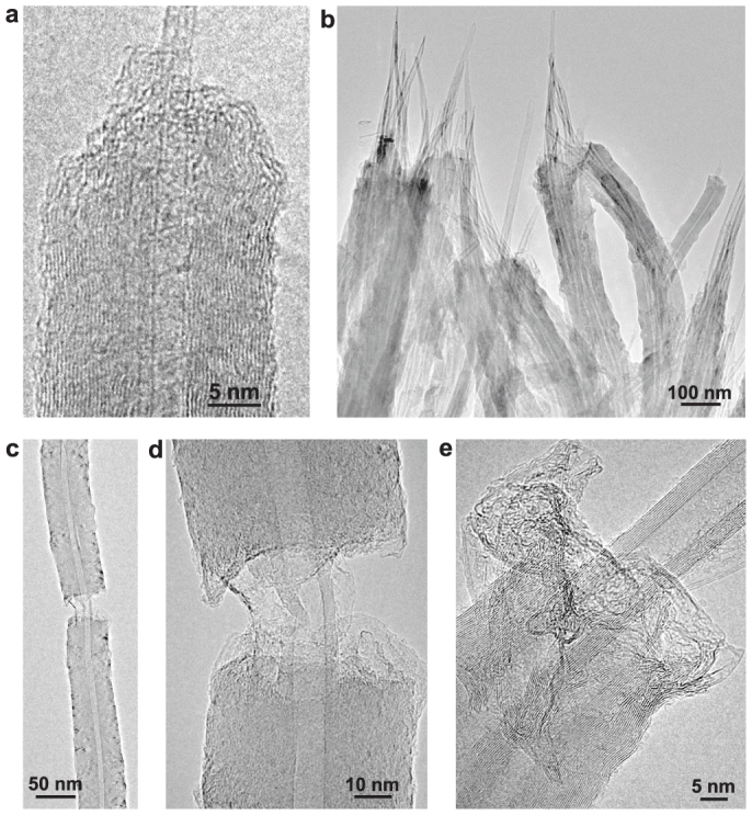
Figure 3. TEM images of fractured nanotubes.

(a), A fractured nanotube showing the pullout of two primary SWCNTs. (b), Several fractured nanotubes showing the pullout of the primary MWCNTs. (c), Low-magnification TEM image showing the fractured graphene segments connected by the primary MWCNT. (d), High-magnification TEM image of the broken part in (c). (e), A fractured nanotube formed by thickening two closely contacted MWCNTs. The images of torn and wrinkled graphene sheets are clearly visible in (a), (d), and (e).
