
Figure 1. Electrochemical nuclear magnetic resonance (EC-NMR) microimaging biofilm reactor.

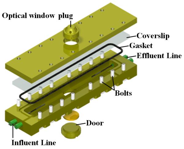
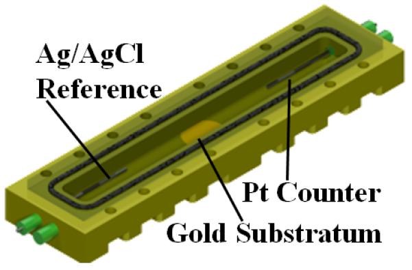
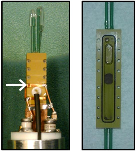
a, NMR setup illustration. The potentiostat and syringe pump were located on a rack outside the 20-gauss magnetic field line of the NMR magnet. Potentiostat wiring and flow perfusion lines entered the magnet bore from below. The growth medium, syringe pump, flow breaker (not shown), and EC-NMR biofilm reactor were kept anaerobic with continually flowing anaerobic gas (20%/80% CO2/N2 for the growth medium). For temperature control, the gas entering the NMR bore was kept at 30 °C. b, The EC-NMR biofilm reactor. The Ag/AgCl reference electrode was located in the inlet perfusion line, entering ~5 mm into the chamber. The working electrode was a 5-mm gold electrode acting as the biofilm substratum, and the counter electrode was a braid of Pt wire inserted into the outlet perfusion line. c, The seated gold electrode completed the bottom flow channel wall, and the top wall was composed of a glass coverslip sealed with a gasket. The electrodes comprising the three-electrode electrochemical cell are labeled. d, Left, the EC-NMR biofilm reactor was seated into a custom-built NMR probe which accommodated an Alderman-Grant-type resonator (arrow), which generated a radio frequency field aligned parallel with the gold electrode. Right, the opened EC-NMR biofilm reactor displaying a Geobacter sulfurreducens biofilm tightly associated with the gold electrode, which functioned as the sole terminal electron acceptor for the system. The biofilm shown is a dark grey, as opposed to the typical vibrant pinkish orange, because of UIV precipitates in the biofilm matrix.