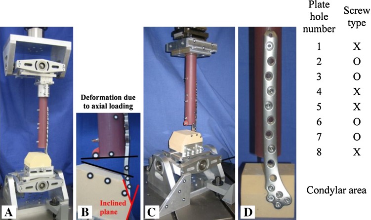
Fig. 2A–D.
(A) Test setup for eccentric axial loading using a cardanic joint distally and proximally. (B) Deformation of the construct resulting from axial loading. Note the inclined plane of 33° for anatomical fit of the plates. (C) Torsional loading was realized with a cardanic joint distally and two horizontal linear bearings proximally. (D) Example of the standardized screw configuration in the shaft area of the bone implant constructs with four bicortical screws: 1 = most proximal plate hole; X = bicortical locking screw; O = no screw/empty plate hole; 8 = distal.

