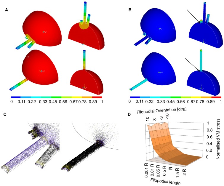
Figure 5. Finite Element models of non-spread growth cones.
(A) Displacement field for FE models of a non-spread growth cone with three (up) and one (down) emerging filopodium. The displacements were normalized over the global maximum over the whole non-spread growth cone, which accounted for the contraction of the neuritic cytoskeleton. The distribution of displacement was linear and similar among different filopodia (up). It was also similar to the displacement distribution of the model with one emerging filopodium (down). (B) Von Mises stress field for FE models of a non-spread growth cone with three (up) and one (down) emerging filopodium. VM stresses were normalized over the maximum stress at the tip of the shortest filopodium. Unlike the displacement field, the VM stresses varied among filopodia of different lengths. In particular, the course of VM along the shortest filopodium was similar for both models with three and one emerging protrusion. Arrows pointed the investigated local maxima of VM stress at the intersection between non-spread growth cones and filopodia for both models (up and down).(C) Vector plots of principal stresses for both models; left: magnification of the vector field for the model with three emerging filopodia; right: magnification of the vector field for the model with one emerging filopodium. In this case also, both fields were similar but scaled. (D) Modular surfaces accounting for the variation of intersection VM stress with filopodial orientation and length. The plot accounted for angular variation in the range (−10°, 10°) and different length of filopodia in the range 0.001 –2
–2 where
where  was the radius of the non-spread growth cone. All values were normalized on the interface VM stress at 0° for a length of 0.001
 .
.

