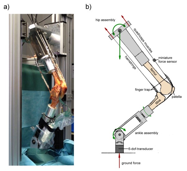
Figure 2.
Composition of the Munich knee rig a) natural specimen with a pressure sensitive film on the retropatellar surface (Tekscan Inc.) tested in the rig b) schematic drawing of the rig illustrating the simulated muscles in the sagittal plane. Forces are shown in red and degrees of freedom are represented in green arrows. (Represented in the drawing are: flexion/extension of femur and tibia, internal/external rotation of the tibia, proximal/distal translation of the femur; not represented are: medial/lateral translation and varus/valgus position of the tibia).

