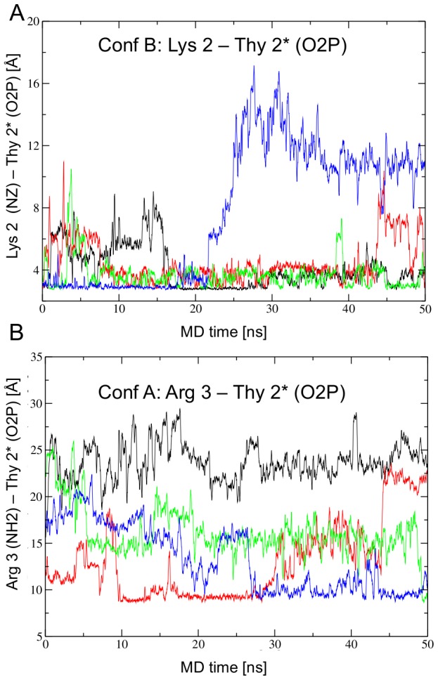
Figure 3. N-terminal arm contacts in the crystal simulation.

A) In Conformation B, the N-terminal arm is mostly ordered with Lys 2 hydrogen bonding with the base of Thy 2* O2P. In model B4 (blue) the N-terminal arm escapes from the minor groove. B) The N-terminal arm in Conformation A starts the simulation disordered. Lys 2 never enters the minor groove, but Arg 3 enters the minor groove in model A2 (red), A4 (blue), and it seems to do so at the end of the simulation in A3 (green). The colors represent one of the four asymmetric units as depicted in Figure S1: A1, B1 black; A2, B2 red; A3, B3 green; A4, B4 blue.
