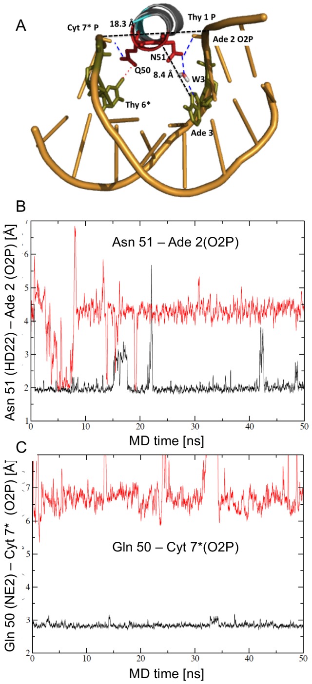
Figure 4. Contacts by helix 3 in the major groove of Conformation A during the solution simulation.

A) Ribbon diagram looking into helix 3 and the major groove. Gln 50 and Asn 51 (labeled as Q50 and N51) contact the phosphate backbone only, with Cyt 7* and Ade 2, respectively (blue dashed lines). Gln 50 is within van der Waals contact of Thy 6* C7 (green, connect by a red dotted line). About 7% of the time a water molecule (W3) mediates contact between Asn 51 and Ade 3 (green). The position of helix 3 in the major groove is measured by the distance between Asn 51 C-alpha to Ade 3 N7 (8.4 Å), and the width of the major groove: Thy 1 P – Cyt 7* P (18.3 Å). The structure represents interactions at 30 ns of the simulation. B) Asn 51 contacts the backbone of Ade 2 O2P only in Conformation A (black), not in Conformation B (red). C) Gln 50 contacts the phosphate backbone of Cyt 7* O2P only in Conformation A (black), not in Conformation B (red).
