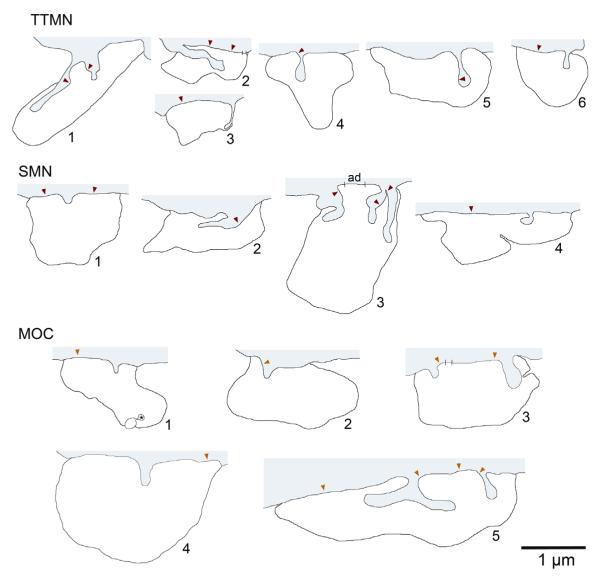
Fig. 2.
Schematic representations of spine-associated terminals from the three groups of neurons. In each case, gray shading at the top indicates the target neuron and its spine(s), and the white outline below indicates the spine-associated terminal. Red arrowheads mark centers of synapses. Hatch marks delineate adherens junctions (the one on SMN terminal 3 marked “ad”). The adherens junction on MOC terminal 5 was not indicated for clarity - it is “behind” the bi-pronged spine (see Fig. 3). One terminal (MOC terminal 1) had an additional spine (asterisk) that originated from an unknown source. Three of the terminals illustrated here also appear in Fig. 1 (TTMN terminal 5, SMN terminal 3, and MOC terminal 5). MOC terminal 4 was the only terminal from an AChE-stained case, and appeared on a distal dendrite.

