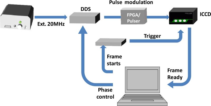
Figure 2.
Schematic of the electronic synchronization signals. The DDS was synchronized with the white laser and controlled by a computer to generate the sinusoidal signal. In the sine-modulation method, this phase-controlled modulation signal was attenuated by 20dB before sending to ICCD. The input signal, Vin=100mV, was amplified by a 36dB internal power amplifier. The amplified modulation signal Vpp = 6.4V together with the variable DC offset was applied to the photocathode of the image intensifier to control the on/off. In the pulse modulation method, the sinusoidal signal from DDS was sent to a pulse generator, which was built with a FPGA board, Xilinx Spartan 6, to convert the sinusoidal waveform to a pulse train. The input signal to the ICCD was also controlled to be 100mV. When ICCD was ready, the computer sent two signals to advance the phase of the modulation signal and trigger the ICCD to acquire images. Phase images were then transferred to the computer via a USB port and analyzed by SimFCS software.

