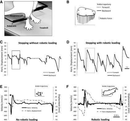
Fig. 1.

Robot arms were attached to the ankles of rats (A). The diagram of the ankle trajectory (B) shows that a downward force was applied whenever the ankle moved backward. In B, forward and backward movements of the ankle during the step cycle are indicated by the dashed and solid lines, respectively. Arrows show direction of ankle movement. Vertical lines are the downward forces applied by the robot on the ankle. The force calibration bar is 10 g. Examples of horizontal (Horiz.) movement of the ankle are shown for 1 rat stepping without robotic loading (C) and with robotic loading (D). Forward and backward movements are indicated by the dashed and solid lines, respectively. The data shown are from 12 s of training performed at week 4. Horizontal velocity and movement of the ankle during 1 step cycle is shown during stepping without robotic loading (E) and with robotic loading (F). The data shown are from step cycles indicated by the boxes in C and D. The corresponding ankle trajectory with directional arrows is shown in the top right sides of E and F.
