
Figure 5. A Model Based on Experimentally Determined Synaptic Conductances Captures Linear Transformation of Pyr Cell Responses.
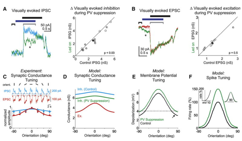
(A) Left: visually evoked inhibitory postsynaptic currents (IPSC) recorded in a Pyr cell during control (cyan) and PV cell suppression (green). Average of 38 sweeps at each condition. Horizontal bars: black, stimulus presentation; blue, LED illumination. Brackets: black, baseline; gray, time over which average IPSC amplitude is computed. Right: scatter plot of visually evoked inhibitory conductance in control versus during PV cell photo suppression (open circles); “X” marks individual cells with significant change in conductance. Solid circle illustrates mean. Average decrease ∼10%; n = 13; p < 0.03.
(B) Left: visually evoked excitatory postsynaptic currents (EPSC) recorded in a Pyr cell during control (red) and PV cell photo suppression (green). Average of 62 sweeps at each condition; horizontal bars and brackets as above. Note that while there is no change in the visually evoked EPSCs relative to baseline (black bracket), a significant increase in EPSC amplitude occurred systematically at led onset (asterisk; 0.1 ± 0.02 nS; n = 10; p < 0.004). Right: scatter plot of visually evoked excitatory conductance in control versus during PV cell photo suppression (open circles); “X” marks individual cells with significant change in conductance; solid circle illustrates mean. Excitatory conductance did not change significantly; n = 10; p = 0.5).
(C) Top: visually evoked IPSCs (cyan) and EPSCs (red) recorded in a layer 2/3 Pyr cell during the presentation of six sinusoidal grating orientations. Bottom, dots: summary of excitatory (red; n = 4) and inhibitory (cyan; n = 5) tuning as a function of orientation. Error bars are the SEM. Lines are the respective Gaussian fits.
(D) Tuning of excitatory synaptic conductance (red) and inhibitory synaptic conductance (cyan: control; green: during PV cell suppression, i.e., 10% reduction) as a function of orientation. Lines are the Gaussian fits from (C).
(E) Net depolarization in the membrane potential of modeled cell (resulting from conductances in D) as a function of orientation under control conditions (black) and during PV cell suppression (green). The dotted line illustrates the spike threshold. Note that under control conditions the membrane potential is above threshold at most orientations.
(F) Model cell's orientation tuning, i.e., firing rate as a function of orientation under control conditions (black; OSI = 0.67; HWHH = 24 degrees) and during PV cell suppression (green; OSI = 0.59; HWHH = 26 degrees). Inset, left: the expansive nonlinear threshold or power law, i.e., the firing rate as a function of net membrane potential depolarization. Inset, right: orientation tuning curves in normalized to the peak. A 10% decrease in inhibition, as experimentally determined, results in ∼50% increase in spiking response at the preferred orientation, a modest decrease in OSI (ΔOSI = 0.08), and a negligible change in tuning sharpness (ΔHWHH = 2 degrees).