Abstract
The very first microfluidic device used for the production of 18F-labeled tracers for clinical research is reported along with the first human Positron Emission Tomography scan obtained with a microfluidically produced radiotracer. The system integrates all operations necessary for the transformation of [18F]fluoride in irradiated cyclotron target water to a dose of radiopharmaceutical suitable for use in clinical research. The key microfluidic technologies developed for the device are a fluoride concentration system and a microfluidic batch reactor assembly. Concentration of fluoride was achieved by means of absorption of the fluoride anion on a micro ion-exchange column (5 μL of resin) followed by release of the radioactivity with 45 μL of the release solution (95 ± 3% overall efficiency). The reactor assembly includes an injection-molded reactor chip and a transparent machined lid press-fitted together. The resulting 50 μL cavity has a unique shape designed to minimize losses of liquid during reactor filling and liquid evaporation. The cavity has 8 ports for gases and liquids, each equipped with a 2-way on-chip mechanical valve rated for pressure up to 20.68 bar (300 psi). The temperature is controlled by a thermoelectric heater capable of heating the reactor up to 180 °C from RT in 150 s. A camera captures live video of the processes in the reactor. HPLC-based purification and reformulation units are also integrated in the device. The system is based on “split-box architecture”, with reagents loaded from outside of the radiation shielding. It can be installed either in a standard hot cell, or as a self-shielded unit. Along with a high level of integration and automation, split-box architecture allowed for multiple production runs without the user being exposed to radiation fields. The system was used to support clinical trials of [18F]fallypride, a neuroimaging radiopharmaceutical under IND Application #109,880.
Introduction
Positron Emission Tomography (PET) is an imaging modality relying on the use of molecular probes labeled with positron emitting radionuclides. The method is widely used in clinical practice with millions of patients scanned annually. A vast majority of the clinical studies are performed with [18F]-2-deoxy-2-fluoro-D-glucose (FDG). Despite its tremendous success in medical imaging, especially in oncological applications, this tracer does not cover all clinical needs.1 To provide physicians with additional information about disease other tracers are being developed. Some of them are at the late stages of clinical trails and anticipated to become commercial products within the next 2 years.2
Production of multiple PET drug products will put significant pressure on PET radiopharmaceutical production facilities. New PET imaging tracers will likely be more demanding technically and manufacturers will have to perform more sophisticated syntheses and operate a wide range of equipment needed for the successful production, purification, and quality control release testing of a variety of molecules. In order to address this new challenge, new approaches for radiochemistry instrumentation are being developed.3 In particular, microfluidic machines are especially promising for the production of radiopharmaceuticals.4,5 A multitude of prototypes was proposed for research purposes and Advion Bioscience currently offers a commercial system under the “Nanotek” brand. However, to the best of our knowledge, no microfluidically produced radiopharmaceutical has been injected in humans until now.
The development of microfluidic systems for radiochemistry has been traditionally focused on the optimization of one key step – fluorine incorporation. Flow-through reactors therefore were an approach of choice because of the enhancement in fluorine incorporation,6,7 and because the manufacturing process was well developed for other microfluidic systems.8 Several reviews cover recent progress in this field.9,5,4
The overall output of a radiochemistry system is however a product of the efficiencies of many processes: transfer of fluoride anion from the water phase to anhydrous solution, radioactivity incorporation, additional chemical transformations, purification, reformulation, and sterile filtration. It also inversely depends on time.
Several features of the flow-through reactors impede their adoption for clinical practice. The first flow-through reactors needed to be primed before they achieved the specified reaction parameters. Priming is achieved by pushing some of the working solutions through the reactor to waste. That inevitably reduces overall efficiency.10 Secondly, the total volume of the reaction mixtures processed in these reactors can be as high as 0.4 mL.11 This dilution gives rise to two problems: diminished concentration of radionuclide in the reaction mixture and an increased amount of organic solvent in the mixture to be purified.
Irrespective of the reactor type, microfluidic systems have to interact with macro-systems. Specifically, a microfluidic device receives milliliter-scale volumes of irradiated water from a cyclotron and then has to produce milliliter-scale volumes of the final product. Efficient conversion from the macro-scale to micro-scale is in development stage so far, although interesting reports of fluoride concentration with absorbents12,13 and electrochemical devices14,15 have appeared recently.
Device description
The device presented here can be considered as a set of functional blocks, namely: a fluoride trap and release system, a reagent delivery system, and a reactor assembly including a heater assembly (Fig. 1, ESI Fig. S5†). High Performance Liquid Chromatography (HPLC) purification and reformulation systems were also connected to the main synthesis unit. The unit was controlled by a programmable logic controller coupled with a PC supporting graphical user interface.
Fig. 1.
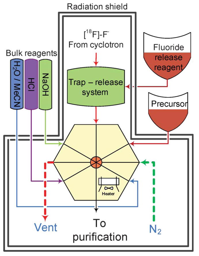
General scheme of the synthetic module. The microfluidic reactor with 8 valved ports is connected to a gas inlet, precursor delivery system, bulk reagent supply and fluoride trap-release system. The final product is transferred to a purification system.
Trap-and-release subsystem
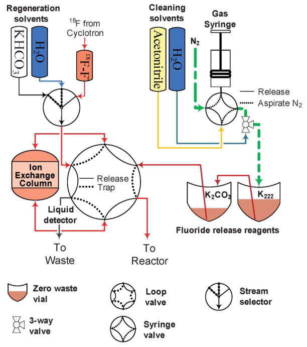
The trap-and-release subsystem (Fig. 2) is based around an ion-exchange cartridge designed specifically to enable the transition of 18F-fluoride from milliliter to microliter volume. Irradiated target water from the cyclotron is delivered into the [18F]F− vial. Once the delivery is finished, the distribution valve is switched to the 18F vial, loop valves are rotated to the “Trap” position, and the fluoride vial is pressurized. Trapping is achieved by passing the irradiated target water through the ion exchange column from the fluoride vial to the [18O]H2O vial.
Fig. 2.
Fluoride trap-and-release system. The micro ion-exchange column is attached to a loop valve. In the trap position the fluoride solution is pushed through the column, in the “Release” position the contents of the release reagent vials are pushed through the column to the reactor.
The column volume is 5 μL and it is packed with AG-1 X8 200–400 mesh resin (Optimize Technologies, Inc). Normally, for a new cartridge, a pressure of 0.69 bar (10 psi) is sufficient to pass 2 mL of water in 1–3 min. The cartridge was shown to be capable of trapping up to 259 Gigabecquerel (GBq) of [18F]fluoride from 2 mL of target water, depending on the specific activity of the fluoride. In the experimental setups used in this study normally no less than 95% of activity was trapped out of as much as 111 GBq (3 Ci). No performance deterioration of the cartridge was observed after more than 50 runs. Trapping of radioactivity is automated by using an optical bubble detector installed downstream from the cartridge (see ESI for a detailed algorithm description†).
The release of the absorbed radioactivity from the column to the reactor is performed by pushing multiple portions of the release solution through the column. A fixed volume of gas (typically 1–2 mL) is dispensed into the first fluoride release solutions vial from a syringe pump and the step is considered finished once the delay time expires.
Column regeneration is performed by passing 3 mL of 0.5 N solution of KHCO3, followed by 3 mL of deionized water. The quality of deionized water used in regeneration is important for trapping efficiency. Due to a minute amount of sorbent in the cartridge, even small amounts of anions in the water reduce the number of available binding sites on the resin. After regeneration the column retains less than 0.1% of the trapped amount of radioactivity.
Remote fluid delivery subsystem
The unit is based on “split-box” architecture: all reagents used in the synthesis and clean cycle are organized on a rack mounted outside of the radiation shields (Fig. 1). Transfer of the reagent inside the shields can be performed in several distinct ways, depending on the volume of reagent available: microliter quantities of valuable reagent, milliliters of bulk reagents or microliter volumes of a reagent available in bulk quantity.
The reagents used in microliter quantities (reagent solutions, fluoride release reagent) are transferred in a manner similar to the release solution (Fig. 3A). They are premeasured into small V-shaped vials and mounted onto fixtures with two metal needles: one for the gas supply and one for the reagent delivery. The vial is pressurized by the dispensing of a measured amount of nitrogen from a micro-syringe and the reagent arrives at its destination after some delay. Teflon tubing is essential to minimize the amount of the reagent left in the tubing after delivery. Tubing made of other polymers, such as polyethylene or PEEK retained more solution. The 0.04″ ID Teflon tubing allows for 95% of a 45 μL bolus of water to be delivered as far as 20 feet away from the vial if the syringe pump dispenses gas no faster than 10 μL s−1.
Fig. 3.
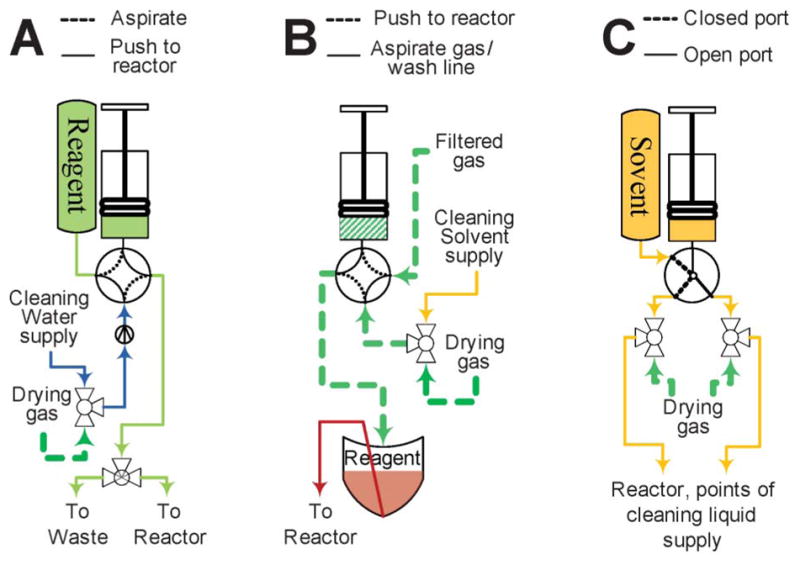
Delivery systems by volumes of liquid transferred. (A) Micro-volume from bulk supply vial; (B) Micro-volume from zero-waste vial; (C) Macro-volume from bulk supply vial. See Fig. 2 for pictogram description.
The reagents used in milliliter quantities are delivered directly by syringe pumps (Fig. 3C). This method is used for flushing the reactor with solvent and during the clean cycle.
Micro-quantities of solutions available in excess, such as solutions of HCl or NaOH, can be delivered in a similar manner (Fig. 3B). However, the line connecting the rotary valve and reactor has to be filled with the solution. For that purpose a miniature three way solenoid bypass valve is installed on the interface base of the reactor (see Fig. 4, right). After priming, no more than 5 μL of air is left in the system. This mode of delivery is necessary for the addition of small volumes into the partially filled reactor, since only 5 μL of gas has to be bubbled through the solution in the reactor. Automation of the procedure proved to be challenging probably due to liquid inertia and tubing pliability. Production experience showed that after the line was primed the syringe had to be programmed to dispense a volume considerably exceeding the volume needing to be delivered. Approximately 15 μL of liquid is needed to bring 10 μL of liquid to the reactor. That might be explained by the fact that valves and tubing in the delivery path exert significant back pressure and the tubing immediately adjacent to the rotary valve expands during delivery. After the syringe stops, the liquid accumulated in the expanded volume slowly keeps moving into the reactor often overfilling it. Careful timing of the on-chip valve closure alleviates the problem.
Fig. 4.
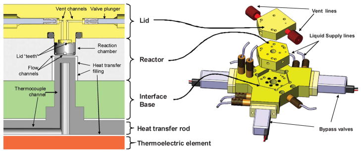
Main parts of the reactor assembly. Left: schematic cross-section of the reactor cavity, lid and heater. Right: 3D rendering of the same parts.
Reagents delivered in bulk (regeneration solutions for the ion exchange column, solutions used in the reformulation process) do not require any precision delivery and are transferred by pressurizing their containers for a defined time period. The reformulation system also utilizes a small solenoid pump for fast delivery of tens of milliliters of diluent.
Microreactor subsystem
The microreactor assembly consists of 3 main components: an injection-molded microfluidic chip; a transparent lid precision-machined out of pDCPD (Materia, Inc.), and an interface base machined out of PEEK. The assembly is mounted on top of the heating system. A microscope camera capturing live video of the processes in the reactor is located above the reactor lid.
The microfluidic reactor chip is manufactured from PEEK, a chemically inert, thermally stable plastic. An injection molding process was developed that allowed the cheap ($500 per 100 units) production of the reactors conforming to the tolerance specifications. The reactor cavity is cylindrical, 5 mm in diameter and 3 mm deep, with a total volume of 60 μL. Some of this volume is taken up by the lid features, resulting in a total usable volume of approximately 50 μL. Thermal exchange with the heater occurs through the reactor floor – a 0.25 mm thick layer of PEEK. This is the part limiting the lifetime of the reactor, averaging 40 production runs. To minimize random failures, the reactor is replaced every 20 runs. Fig. 4 outlines the architecture of the reactor assembly.
The six flow channels (0.6 mm diameter) are distributed evenly along the bottom edge of the reactor. Pneumatically actuated two-way on-chip valves (Fig. 5) connect flow channels to the reagent delivery subsystems. Depending on the pressure used in the actuator, the valve can withstand pressures of up to 20.68 bar (300 psi) inside the reactor. The seal along the side of the plunger is only provided by friction forces, pressure from the inlet channel can not exceed 2.07 bar (30 psi). This limitation is not relevant for practical purposes as this seal is only needed during reagent delivery.
Fig. 5.

Schematic representation of the valve mechanism.
The cylindrical reaction chamber was created by assembling two components—the reactor and its lid—that are press-fitted together, blocking all leaks at their junction. The lid is manufactured from polydicyclopentadiene (pDCPD) – a transparent and relatively stable material. Two valves identical to the reactor ones were built in the lid for gas inlet/outlet. Rapid removal of solvent vapors occurs when carrier gas is passing over the surface of the liquid. The unique architecture of the lid prevents reactor content from escaping during the filling and evaporation steps.
The lid material had to satisfy several criteria: transparency, chemical stability, radiochemical stability and suitability for machining. Transparency had to be sufficient to permit the use of a camera to monitor the processes inside the reactor. Machinability was important to form the minute features with small tolerances. pDCPD satisfies nearly all criteria, but its stability to acids is only moderate. In the presence of strong acids it loses transparency and can withstand no more than 10 production runs. It can also leach polymer degradation products into the reaction mixture. The transparent machinable fluoropolymer Teflon© AF was tested, but its chemical stability was not sufficient for radiochemical purposes: the amount of fluoride anion escaping this particular grade of Teflon had a severe effect on the specific activity of the final radiopharmaceuticals. Several types of glass inserts were tested as well, but the reliable production of glass pieces of such a complex shape proved to be challenging.
The interface base is the part onto which the reactor chip is physically mounted. It couples the reactor chip to heating elements and the reagent delivery systems adapting liquid plumbing built around conventional 1/16 inch (1.6 mm) OD tubing to liquid passages of the microreactor. Bypass valves for the bulk reagent delivery systems are mounted directly on the base.
The heating assembly is based on a thermoelectric silicon sealed module (6 ampere, 19.5 volt max) with a thermo-conducting aluminum rod coupling the heating element to the floor of the reactor. The heater is controlled by a hardware controller, which gets feedback from a thermistor mounted inside the heat-transferring rod.
HPLC subsystem
HPLC purification and reformulation subsystems generally follow the architecture common for macro-scale devices, but allow for the collection of multiple fractions during HPLC purification (see ESI for the schematic†). The HPLC part consists of a loop valve for the column loading, HPLC column and a fraction selector valve. Eluent flow is provided by a programmable gradient pump (Jasco PU 2089i). Two detectors are mounted in between the column and the selector valve: an in-house built UV-flow cell and a radiation detector. Two optic fibers connect the flow cell to the light source (Hammamtsu L10290) and spectrophotometer (Ocean Optics USB4000 UV-Vis). This design provides spatial separation of the flow cell and the light source/detector and is an important advantage strengthening the split-box concept. The radiation detector is based around a Carol & Ramsey Associates 105S-1 detector. Both the photon counting and integrated analog outputs of the amplifier are read by a data acquisition board and displayed to the user. The fraction selector has 6 positions, 1 reserved for the routing of the waste and one is preprogrammed for the collection of a fraction for later reformulation.
Software
The software driving the device can operate in two modes: manual and automatic. In manual mode, the user has full control over the components of the system, dictating the position of the valves, temperature setting, pressure and syringe pump operations. In the automatic mode, software drives specific unit operations according to parameters defined by the user. For instance, in unit operation “Evaporation” the user defines the time, temperature and pressure of the nitrogen. Several unit operations are preprogrammed and they can be linked together in a full recipe.
Discussion
We present a detailed report on the architecture of a fully integrated microfluidic system suitable for clinical production of PET radiopharmaceuticals. The device has been qualified for the clinical production of several PET radiotracers including the proliferation tracer [18F]-3′-fluoro-3′-deoxy-L-thymidine ([18F]FLT)16 and the hypoxia tracer 3-[18F]fluoro-2-(4-((2-nitro-1H-imidazol-1-yl)methyl)-1H-1,2,3-triazol-1-yl)-propan-1-ol ([18F]HX4).17 Its applicability for clinical production has been demonstrated in the clinical trials of [18F]fallypride at the University of California, San Diego. It has also been extensively validated for preclinical use in several radio-pharmacies including centers at Massachusetts General Hospital, University of California at San Diego, Siemens MIBR and Oxford University.
The system is based on a 50 μL microfluidic batch reactor. In one production run, it uses the entire amount of [18F]fluoride produced by the cyclotron. In this way the concentration of fluoride is increased by an order of magnitude compared to the conventional milliliter-scale reactors18 or flow-through systems lacking a concentration mechanism.19 An increased concentration of fluoride can positively affect the rate of fluoride incorporation, since fluoride concentration is the rate limiting step of this bimolecular process. Due to the low reactor volume, the amount of precursor required to maintain the desired concentration is also lower. A reduced amount of precursor translates into obvious cost benefits, but also simplifies the purification process as smaller HPLC columns are needed to handle the lower mass of impurities.
The transition from macro- to micro-scale is a problem common to all microfluidic systems. The low volume reactor inevitably needs to be coupled to high-volume parts of the system: the dilute solution of fluoride comes from the cyclotron on one side and the dilute solution of the final product goes to the purification system on the other. Translation from macro-scale to micro-scale is facilitated by concentration of the fluoride on a micro-scale anion-exchange column. Transition back to macro-scale is not a prerequisite for the successful production, but is dictated by the fact that the reactor is designed to hold its content and it requires a large volume of solvent to completely elute the reaction mixture out. Dilution of the radioactive drug also minimizes radiolysis.
The device implements the idea of a split-box: a system where the components that the operator interacts with are located outside of the shields. To that extent, all functional components are mounted on a frame and housed inside the shielded space (hot cell), while the reagent rack and a controlling computer are located outside of the hot cell. This architecture allows users to deliver reagents and perform cleaning of the instrument without direct access to the high radiation area inside the hot cell.
The split-box design provides advantages going far beyond radiation safety and convenience. Full automation of the clean cycle frees the operator to prepare for the next run while the device is going through an automated clean cycle, thus increasing efficiency of the workflow. As a result, as many as 20 process optimization runs in a day were performed on the device. When HPLC purification was included in the protocol as many as 6 runs in a day could be accomplished. Inclusion of clinical-level quality control of the final product increased the production time even further, but 3 clinical qualification runs still could be performed in one day. At the development stage, the high turnover rate allows fast conditions optimization on exactly the same equipment later used for the actual production. Each parameter of the protocol can be sampled individually, without day-to-day variability typical of radio-chemical research.
In the production environment, an option to correct for deviations confers significant practical advantage. In the case of a conventional system, production runs can not be repeated until the radioactivity in the synthetic unit completely decays, normally by the next day. Therefore, in the case of operator error, for instance a reagent loaded in the wrong position, the dose production fails. The split-box allows the operator to start cleaning the instrument then repeat the production immediately after the error is exposed, and still deliver the dose only with marginal delay. This is a very important feature increasing reliability of the production process.
The system presented here provides the user with visual information on the processes occurring in the reactor. Microfluidic systems require specialized technologies for gathering process information20–22 and live images of the reactor can be very informative in this situation. Drying, elution and reactor filling can be monitored visually and it is an attractive goal to develop image analysis software automating the monitoring of these processes.
The main application of such a system is the development and production of 18F-labeled tracers for positron emission tomography (PET). Batch reactors are particularly suitable for the production purposes as they follow the same workflow as other equipment involved in the imaging study: production of one batch of the product at a time. For a typical production run radioactivity is generated in the form of a solution in 18O-enriched water. The water has to be removed and the radioactivity needs to be re-dissolved in an anhydrous medium. This is typically achieved by the trapping of the [18F]fluoride on an anion exchange cartridge followed by washing of the cartridge with a release solution. The release solution is then evaporated to dryness and in some cases an additional portion of solvent is added and evaporated again to remove traces of moisture. The precursor solution is then added and the reaction chamber is heated for a specified time at a defined temperature. Several sequential reactions might be required to complete all transformations necessary, the most common sequence including de-protection of the precursor after the fluorination step. The crude reaction mixture then needs to be transferred to the purification system and the purified fraction might require reconstitution in a solvent suitable for intravenous injection. Below we discuss each step as it is implemented in the present instrument.
[18F]fluoride trapping and release
In the presented system, the solution of [18F]fluoride is delivered from the cyclotron to the [18F] vial of the trap/release subsystem. For the accurate accounting of the radioactivity delivered, the vial is located in a dose calibrator. Upon completion of delivery the solution is pushed through the ion exchange cartridge at a rate of ~1 mL min−1. Trapping is controlled with an optical liquid detector downstream from the ion exchange column (Fig. 2).
Trapped fluoride can be released with a variety of reagents ranging from a water solution of Cs2CO3 to an MeCN–water solution of n-Bu4NHCO3. Release efficiency is greatly affected by the concentration and the nature of the base. Milder bases, such as KHCO3 can be used as well as K2CO3, but require higher salt concentration to achieve the same release efficiency. A concentration of K2CO3 of no less than 5 g L−1 or KHCO3 of no less than 10 g L−1 is required for efficient release.
Dividing the release solution into multiple portions greatly increases the release efficiency. In the case of the K2CO3/2.2.2-cryptand (Kryptofix, K222) mixture (5 g L−1 and 7.5 g L−1 respectively) dividing the solution into 3 boluses resulted in a 50% increase of release efficiency, however increasing the number of boluses to 16 only led to a marginal improvement. To generate several boluses the solution is split into two uneven parts loaded in the vials “K2CO3” and “K222”. When the syringe dispenses gas into the K222 vial its content starts moving up the line connecting the two vials and compresses gas in the “K2CO3” vial. The volume of the line is chosen in such a way that carbonate leaves the vial before the first drop of K222 solution comes in, thus creating a separate portion of solution travelling toward the column. As the K222 solution comes into the vial, it drips from the tube and forms separate liquid portions as it starts moving toward the column. For the K2CO3/K222 mixture typically used for radiofluorination the optimal composition of the two solutions was found: 7 μL of aqueous K2CO3 followed by a mixture of 7 μL of aqueous K2CO3 and 30 μL of K222 in MeCN.
The process is monitored with a low-sensitivity pin-diode radioactivity detector (Carol-Ramsey 101HDC-3) mounted on the ion exchange column. Fig. 6 represents the graph obtained when 13.7 GBq (370 mCi) of 18F− were delivered from the cyclotron, trapped on the ion exchange column and then released. The rapid increase in the radioactivity at the beginning of the graph corresponds to the trapping phase. It is followed by a plateau corresponding to the compression phase of the release reagent delivery. As each bolus of the delivery reagent passes through the column, radioactivity drops sharply. In this particular example four major boluses passed through the column during the release phase. The signal from the detector does not go all the way down at the end of the process due to the fact that the detector has no shielding and is affected by radioactivity already transferred to the reactor. Detailed evaluation of the trapping and release efficiency can be only performed by measurement of all liquids in a well counter.
Fig. 6.
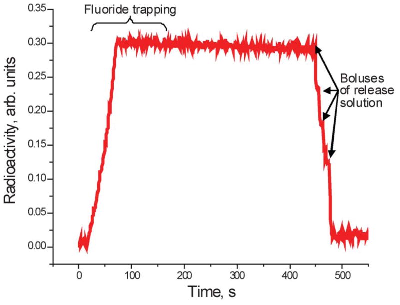
Radioactivity trace obtained from the detector installed on the ion exchange column during the trap-release process.
The ion exchange cartridge can be cleaned and regenerated without operator exposure, increasing the number of runs performed in a day. Use of disposable cartridges would require a complex mechanical system for replacement of a cartridge, or a complex routing of fluids to pre-installed cartridges, while a cleanable cartridge avoids this complexity.
The release process described above and low internal volume of the column ensure the high concentration efficiency of the system. In the presented system, the amount of fluoride delivered to the reactor is dissolved in no more than 45 μL. Conventional ion exchange cartridges concentrate [18F]fluoride to 400–1000 μL;23,24 the concentration system of commercial microfluidic devices reduces the volume of fluoride solution to 400 μL.11
Evaporation
Multistep chemical syntheses in microfluidic devices is complicated by the fact that each transformation requires its own set of conditions, in particular its own solvent. In bulk syntheses, the problem is overcome by evaporating the solvent from the product of one step and dissolving the residue in a solvent more conducive for the next. With the exception of the very recent report of a EWOD chip,25 microfluidic designs reported to date5 do not address the problem of efficient on-chip evaporation. The main obstacle for efficient evaporation is the loss of liquid with the egress of vapors. One approach to solving this problem for batch microreactors is the use of gas-permeable membranes that allow the passage and removal of solvent vapors.13 However, the membranes commonly employed for the manufacture of the microfluidic devices are not stable in organic solvents and strong bases often used in radiosynthesis.26 In addition, organic solvents can not be overheated in this type of reactor because membranes cannot withstand high pressures; also their permeability can not be regulated, which leads to evaporation during the stages where the solvent volume should be maintained stable.
The reactor subsystem of the device developed in this study is based on a membrane-free high-pressure batch microreactor assembly allowing gas and vapor egress without the loss of liquid contained in the reactor.
Liquids are evaporated from the reactor by passing a stream of dry gas across the liquid surface, while maintaining an elevated temperature in the reactor. Evaporation completion is determined visually with the integrated camera (Fig. 7, see ESI for zoom†). Assuming the flow of gas is unobstructed, the repeatability of evaporation is sufficient enough for the process to be automated based on timing which is determined during the development stage. To monitor the flow of gas through the reactor, a mass flow meter was installed upstream from the reactor lid; typical gas flow during the evaporation step is in the range of 2–10 mL min−1.
Fig. 7.
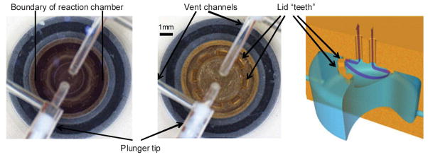
Camera view of the reactor: (a) filled reactor, (b) dry reactor; (c) schematic of the gas flow through the reactor cavity.
To prevent liquid from escaping from the reactor during the evaporation process a circular array of 0.7 × 0.3 × 0.3 mm protruding blocks is machined on the inner side of the lid. This system relies on surface tension to prevent liquids from contacting the vent openings during the reagent filling and evaporation steps. The openings between the blocks allow complete drying of the reaction chamber. The reactor can, therefore, be filled rapidly and can endure high-flow evaporations without forcing the liquid out through the vent. Efficiency of the system is confirmed by the fact that less than 0.5% of the radioactivity is found in the charcoal trap installed in the vent channel downstream of the reactor (Fig. 1).
The time required for the evaporation of 45 μL of the acetonitrile–water mixture did not exceed 5 min. This compares favorably with the time existing radiochemistry systems require to evaporate solutions of a volume relevant to the production process. Macroreactor-based systems, although more efficient for evaporation, have to evaporate significantly larger volumes, therefore total evaporation time is on the scale of 6 to 12 min in these cases.27 A recently developed droplet-based microfluidic device also was reported to accomplish evaporation using a combination of heating with gas flow.25
Small volume reagent addition
To deliver reagent from the zero-waste vial to the reactor the vial is pressurized by dispensing a measured amount of gas from a micro-syringe. The amount of gas is optimized to minimize bubbling after arrival of the reagent to the reactor. With the reactor filled almost to its full capacity, small bubbles of gas coming from the supply line rarely push content into the vent. However, vigorous bubbling leads to vent losses and has to be avoided. For that reason, nitrogen is dispensed in two steps. During the first step the bulk of the gas is dispensed, moving the liquid close to the reactor. A second, slower dispense pushes liquid into the reactor. The automated program closes the on-chip valves after a certain time from the beginning of the first gas push. The time is defined at the development phase and depends mainly on the length of tubing connecting the reagent vial with the reactor.
Reaction
The system does not have any active stirring elements, however we routinely observed >95% incorporation of the starting fluoride in the synthesis of [18F]fallypride. During the time scale typical for radiofluorination in the reactor, diffusion of a small molecule in MeCN should only be significant on a distance not exceeding 0.1 mm.26 The reaction chamber of the system is an order of magnitude larger (see ESI for details on the reactor arrangement†). Therefore, it is likely that convective mixing plays a significant role.
The reaction is normally conducted in a sealed reactor, which can be pressurized before sealing but the total pressure however should not exceed the valve rating of 20.68 bar (300 psi). The heating system is capable of heating the reactor to 150 °C in 30 s, 170 °C in 55 s. The maximum temperature achievable after 10 min of heating is 200 °C. A thermoelectric module can also be used for rapid reaction cooling. This is an important feature as the reactor can only be opened once the temperature of the content is below its boiling point. Even with this precaution, the reactor valve opens with the vent line pressurized to 3.45 bar (50 psi) to avoid potential loss of liquid due to the gases formed during the reaction. The thermoelectric module used in the system likely experiences significant overheating, which limits its operational lifetime. The current design requires replacement of the module every 40 production runs, and alternative solutions are being researched.
Product elution
The product is transferred from the reactor to the HPLC loading loop with an excessive amount of water pushed by a syringe pump. Transfer efficiency is a concern at this step because the reactor cavity is designed to efficiently retain its content. Therefore, a large amount of water is needed to transfer the reaction mixture to the HPLC loading loop. As a result, purification efficiency might be decreased due to HPLC peak broadening. It was reported previously that in the case of a coin-shaped reactor, adjacent ports should be used for inlet of the liquid and the outlet of the mixture.28 Production tests revealed several practical limitations of this approach. Specifically, the passages in the reactor lid are filled with the reaction mixture and this portion of the mixture remains in the reactor long after the bulk of the mixture is already transferred. Also it was discovered that elution performed in several back and forth steps is more efficient compared to one push. So the final protocol of the elution included the dispensing of 600 μL of water followed by aspirating 300 μL of water by the same syringe, repeated three times.
Reaction radiation trace
Fig. 8 illustrates the read-out of a radiation detector installed in the vicinity of the reaction chamber. This particular profile was observed during optimization run of [18F]FLT production. The synthesis consists of fluoride delivery, drying, additional azeotropic fluoride drying, fluorination, evaporation of the reaction mixture, addition of acid and hydrolysis. Most of the radioactivity loss is attributable to radioactive decay. Some fluctuations also occur due to the change in the reaction mixture geometry (note radioactivity increases at the end of fluoride drying step). This particular optimization run demonstrated considerable loss of radioactivity upon depressurization of the reactor at the end of the second step. Although the mixture was recovered during transfer to the HPLC system, this observation indicated that the back-pressure in the vent line had to be increased before opening the vent valve. Note the gradual decrease in radioactivity due to the stepwise elution process.
Fig. 8.
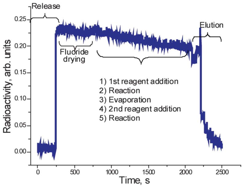
Radioactivity trace from the detector installed on microreactor during a 2-step synthetic procedure including fluoride delivery, fluoride release into the reactor, fluoride drying, addition of a reagent, reaction, evaporation of the solvent, addition of the second reagent, second reaction and product elution.
HPLC purification and reformulation
After the reaction mixture is transferred to the loading loop, the user initiates a purification step which follows a conventional HPLC purification procedure. The output from the HPLC detectors is displayed on the user’s computer screen. Fractions are collected either manually or automatically once the purification protocol is established. A high-pressure stream selector valve is used for fraction collection. One position of the selector is designated for waste collection; one position is reserved for the reformulation system and four positions are used to collect fractions (see ESI for the purification system scheme†). The HPLC fraction containing the tracer of interest is collected in the reformulation vial filled with the diluent and placed on a magnetic stirrer to homogenize the mixture. After the 2–3 min needed for homogenizing, the mixture is pushed through a disposable solid-phase extraction cartridge. To wash the cartridge, the reformulation vial is filled with water from an outside bulk vial and the water is pushed through the cartridge. The tracer is released with a solution from a vial mounted on the reagent rack.
Clean cycle
After the end of synthesis an automated clean cycle can be performed. The clean cycle uses the same reagent delivery methods as described in the previous parts, but delivers copious amounts of water followed by acetonitrile through the respective lines to the reactor. The chip temperature is kept at 60 °C during the cleaning. The reactor exit line is open to the waste collector during the cleaning. After the acetonitrile is pushed through the precursor and K222 lines the reactor and the lines are dried by passing a flow of dry nitrogen for 10 min. Three way valves are dried separately, by pushing a nitrogen flow while turning the valves on and off. The ion exchange column is regenerated in parallel with the clean cycle. All procedures are performed automatically, the total cleaning time is 45 min.
Clinical production of [18F]fallypride
This system was utilized for the production of human doses of [18F]fallypride – a tracer developed by Mukherjee and coworkers29 and currently undergoing clinical investigation for the imaging of D2/3 dopamine receptors in the human brain.30,31 A number of different conditions were reported for [18F]fallypride synthesis, but direct transfer of the conditions from macroreactors to the microreactor does not give optimal results. Therefore, radiochemical yield of the product was optimized by the systematic tuning of the following parameters: reaction temperature, duration of the fluorination reaction, base concentration and strength, solvent composition and the conditions of fluoride drying. High automation of the synthetic module and rapid turn around time allowed as many as six optimization runs (starting from target bombardment to final product isolation in the injectable form) done in one day. This decreased variability in the data and allowed for reduced optimization time. Optimization of the reaction conditions opened an opportunity to improve the HPLC purification parameters. As opposed to the other methods of [18F]fallypride production,32 our microfluidic device produced a reaction mixture amenable for purification with an ethanol–water mixture, thus eliminating the reformulation step. The optimized protocol allowed a 37 ± 5% decay corrected yield of the injectable product in 45 min starting from the unloading of the cyclotron target to the collecting of the final dose (see ESI for more details†).
Fallypride produced on the device was used in an a clinical trial conducted at the University of California San Diego. Twelve patients were injected with the [18F]fallypride produced on the microfluidic device. All doses passed quality control and were found to conform to the requirements of chemical and radiochemical purity, residual solvent content, pH, kryptofix concentration, pyrogenicity and sterility. No failures were reported. On several occasions two patients were scheduled in one day and two production runs were performed in one day on the same instrument.
Fig. 9 presents a typical image from a healthy volunteer obtained with the [18F]fallypride produced on the microfluidic device. The imaging agent obtained on the microfluidic device was substantially equivalent to the tracers produced on the macrofluidic machines. Therefore, the image is expectedly similar to the images reported for the fallypride obtained on the conventional modules.29
Fig. 9.
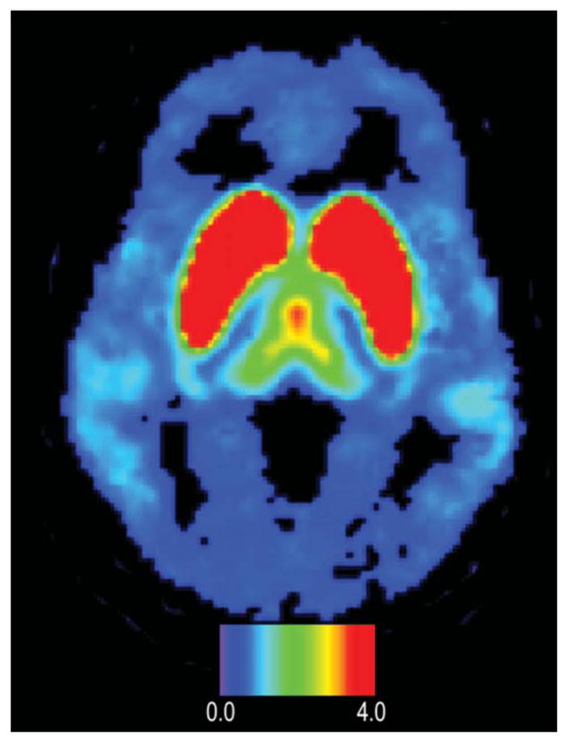
PET image of D2/D3 dopamine receptors distributed in a human brain obtained with microfluidically produced [18F]fallypride. The color bar shows binding potential. Note uptake in temporal lobes and frontal lobe.
Conclusions
We presented the first microfluidic device for the production of clinical research doses of 18F-labeled PET tracers. To the best of our knowledge, this is the first case of a microfluidic device used to synthesize a radiopharmaceutical injected into a human.
Table 1 lists selected operational parameters of radio-chemistry modules reported to date. The system presented in this publication is distinguished by two key microfluidic features: a fluoride concentration system and a microfluidic batch reactor. The concentration system allows for the transition of radioactivity from macro-volumes to micro-volumes, thus enabling the batch microreactor to operate at optimal conditions. The batch microfluidic reactor proves to be particularly suitable for clinical operations as it fits in the workflow of an imaging study, requiring the production of one batch of the tracer at a time.
Table 1.
Operational properties of the presented microfluidic device compared to the conventional module (Tracerlab FX-N™ from GE) and the commercial preclinical microfluidic system (Nanotek™ from Advion)
| This report | Tracerlab FX-N™ conventional module33,18 | Nanotek™ flow-through microfluidic | |
|---|---|---|---|
| Reactor volume | 50 μL | 5 mL | 31.4 μL34 |
| Max pressure in the reactor | 2 MPa | 0.4 MPa | 20 MPa |
| Radioactivity concentrationa | ~20 GBq mL−1 | ~1 GBq mL−1 | ~1 GBq mL−1b,35 |
| Volume of the mixture before purification | 0.7–1 mL | 4 mL | Process-specific |
| Sequential reactions in the reactor | Yes | Yes | No35 |
| Integration with purification | Yes | Yes | No35 |
| Number of production runs per day | 3 (limited by the process time) | 1 (instrument can not be reloaded) | 1 (instrument can not be reloaded) |
| Fluoride drying time | 240–300 s | 300–600 s | 1200 s36 |
Assuming 1 GBq of radioactivity delivered from the cyclotron.
Assuming a 1 : 1 fluoride : precursor ratio.
The “split-box architecture” is an important design feature in the system, with reagents loaded from outside of the radiation shielding. This is critical for performing multiple production and optimization runs in a day. The potential to perform up to 3 full production runs or up to 20 optimization runs in one day was demonstrated. Full automation of preparative steps such as the cleaning and drying of the system was also necessary to achieve high throughput. The system was qualified to produce human doses of several radiopharmaceuticals, including [18F]FLT16 and [18F]HX4.17 Ultimately, its suitability for clinical production was demonstrated in the production of multiple [18F]fallypride doses used in a clinical trial.
Supplementary Material
Acknowledgments
The authors thank Dr Carl Hoh and Alex DeCastro for assistance in image processing; Dr James Lohr, Dr David Walling, Christopher Davis, and Laurel Glockler for assistance in patient recruitment and scanning; and Dr Ramaiah Pichika and Dr William Eckelman for enabling [18F]fallypride production and quality control, which will be reported in a separate publication. Also, the authors thank Ansgar Graw and Leonid Katsnelson for graphic design.
Footnotes
Electronic supplementary information (ESI) available. See DOI: 10.1039/c2lc40853h
Contributor Information
Artem Lebedev, Email: artem.lebedev@siemens.com.
Monte S. Buchsbaum, Email: mbuchsbaum@ucsd.edu.
References
- 1.Endo K, Oriuchi N, Higuchi T, Iida Y, Hanaoka H, Miyakubo M, Ishikita T, Koyama K. Int J Clin Oncol. 2006;11:286–96. doi: 10.1007/s10147-006-0595-0. [DOI] [PubMed] [Google Scholar]
- 2.Vallabhajosula S, Solnes L, Vallabhajosula B. Semin Nucl Med. 2011;41:246–64. doi: 10.1053/j.semnuclmed.2011.02.003. [DOI] [PubMed] [Google Scholar]
- 3.Krasikova R. Ernst Schering Res Found Workshop. 2007:289–316. doi: 10.1007/978-3-540-49527-7_11. [DOI] [PubMed] [Google Scholar]
- 4.Wang MW, Lin WY, Liu K, Masterman-Smith M, Shen CKF. Molecular imaging. 2010;9:175–91. [PMC free article] [PubMed] [Google Scholar]
- 5.Miller PW, de Mello AJ, Gee AD. Curr Radiopharm. 2010;3:254–262. [Google Scholar]
- 6.Bouvet VR, Wuest M, Wiebe LI, Wuest F. Nucl Med Biol. 2011;38:235–45. doi: 10.1016/j.nucmedbio.2010.09.002. [DOI] [PubMed] [Google Scholar]
- 7.Pascali G, Nannavecchia G, Pitzianti S, Salvadori PA. Nucl Med Biol. 2011;38:637–644. doi: 10.1016/j.nucmedbio.2011.01.005. [DOI] [PubMed] [Google Scholar]
- 8.Lu S, Pike VW. In: PET Chemistry, The driving force in molecular imaging. Schubiger PA, Lehman L, Friebe M, editors. Springer; Berlin: 2007. pp. 271–287. [Google Scholar]
- 9.Elizarov AM. Lab Chip. 2009;9(10):1326–33. doi: 10.1039/b820299k. [DOI] [PubMed] [Google Scholar]
- 10.Ungersboeck J, Philippe C, Mien LK, Haeusler D, Shanab K, Lanzenberger R, Spreitzer H, Keppler BK, Dudczak R, Kletter K, Mitterhauser M, Wadsak W. Nucl Med Biol. 2011;38:427–34. doi: 10.1016/j.nucmedbio.2010.09.009. [DOI] [PubMed] [Google Scholar]
- 11.Anderson H, Pillarsetty N, Cantorias M, Lewis JS. Nucl Med Biol. 2010;37:439–42. doi: 10.1016/j.nucmedbio.2010.01.003. [DOI] [PMC free article] [PubMed] [Google Scholar]
- 12.De Leonardis F, Pascali G, Salvadori PA, Watts P, Pamme N. J Chromatogr, A. 2011;1218:4714–4719. doi: 10.1016/j.chroma.2011.05.062. [DOI] [PubMed] [Google Scholar]
- 13.Lee CC, Sui G, Elizarov AM, Shu CJ, Shin YS, Dooley AN, Huang J, Daridon A, Wyatt P, Stout D, Kolb HC, Witte ON, Satyamurthy N, Heath JR, Phelps ME, Quake SR, Tseng HR. Science. 2005;310:1793–6. doi: 10.1126/science.1118919. [DOI] [PubMed] [Google Scholar]
- 14.Wong R, Iwata R, Saiki H, Furumoto S, Ishikawa Y, Ozeki E. Appl Radiat Isot. 2012;70:193. doi: 10.1016/j.apradiso.2011.09.022. [DOI] [PubMed] [Google Scholar]
- 15.Lu S, Clements JT, Gilde MJ, Prak A, Watts P, Pike VW. J Labelled Compd Radiopharm. 2007;50:597–599. [Google Scholar]
- 16.Salskov A, Tammisetti VS, Grierson J, Vesselle H. Semin Nucl Med. 2007;37:429–39. doi: 10.1053/j.semnuclmed.2007.08.001. [DOI] [PubMed] [Google Scholar]
- 17.van Loon J, Janssen MHM, Ollers M, Aerts HJWL, Dubois LJ, Hochstenbag M, Dingemans AMC, Lalisang R, Brans B, Windhorst B, van Dongen GAMS, Kolb HC, Zhang JJ, De Ruysscher D, Lambin P. Eur J Nucl Med Mol Imaging. 2010;37:1663–8. doi: 10.1007/s00259-010-1437-x. [DOI] [PubMed] [Google Scholar]
- 18.Shao X, Hoareau R, Hockley BG, Tluczek LJM, Henderson BD, Padgett HC, Scott PJH. J Labelled Compd Radiopharm. 2011;54:292–307. doi: 10.1002/jlcr.1865. [DOI] [PMC free article] [PubMed] [Google Scholar]
- 19.Wester HJ, Schoultz BW, Hultsch C, Henriksen G. Eur J Nucl Med Mol Imaging. 2009;36:653–8. doi: 10.1007/s00259-008-0985-9. [DOI] [PubMed] [Google Scholar]
- 20.Vu NT, Yu ZTF, Comin-Anduix B, Søndergaard JN, Silverman RW, Chang CYN, Ribas A, Tseng HR, Chatziioannou AF. J Nucl Med. 2011;52:815–21. doi: 10.2967/jnumed.110.078725. [DOI] [PMC free article] [PubMed] [Google Scholar]
- 21.Ross D, Gaitan M, Locascio LE. Anal Chem. 2001;73:4117–4123. doi: 10.1021/ac010370l. [DOI] [PubMed] [Google Scholar]
- 22.Cho JS, Taschereau R, Olma S, Liu K, Chen Y-C, Shen CKFKF, van Dam RM, Chatziioannou AF. Phys Med Biol. 2009;54:6757–71. doi: 10.1088/0031-9155/54/22/001. [DOI] [PMC free article] [PubMed] [Google Scholar]
- 23.Hayashi K, Furutsuka K, Takei M, Muto M, Nakao R, Aki H, Suzuki K, Fukumura T. Appl Radiat Isot. 2011;69:1007–13. doi: 10.1016/j.apradiso.2011.02.025. [DOI] [PubMed] [Google Scholar]
- 24.Moon BS, Park JH, Lee HJ, Kim JS, Kil HS, Lee BS, Chi DY, Lee BC, Kim YK, Kim SE. Appl Radiat Isot. 2010;68:2279–84. doi: 10.1016/j.apradiso.2010.06.016. [DOI] [PubMed] [Google Scholar]
- 25.Keng PY, Chen S, Ding H, Sadeghi S, Shah GJ, Dooraghi A, Phelps ME, Satyamurthy N, Chatziioannou AF, Kim CJ, van Dam RM. Proc Natl Acad Sci U S A. 2012;109:690–5. doi: 10.1073/pnas.1117566109. [DOI] [PMC free article] [PubMed] [Google Scholar]
- 26.Sommer GJ, Chang DS, Jain A, Langelier SM, Park J, Rhee M, Wang F, Zeitoun RI, Burns MA. In: Microfluidics for Biological Applications. Tian W-C, Finehout E, editors. Springer; 2008. pp. 1–34. [Google Scholar]
- 27.Zhang Y, Zhang Y, Wang M, Liu H, Yang Z, Gao Z. Zhonghua Heyixue Zazhi. 2011;31:196–200. [Google Scholar]
- 28.Elizarov AM, Meinhart C, Miraghaie R, van Dam RM, Huang J, Daridon A, Heath JR, Kolb HC. Biomed Microdevices. 2011;13:231–242. doi: 10.1007/s10544-010-9488-0. [DOI] [PMC free article] [PubMed] [Google Scholar]
- 29.Mukherjee J, Christian BT, Dunigan KA, Shi B, Narayanan TK, Satter M, Mantil J. Synapse. 2002;46:170–88. doi: 10.1002/syn.10128. [DOI] [PubMed] [Google Scholar]
- 30.Buchsbaum MS, Christian BT, Lehrer DS, Narayanan TK, Shi B, Mantil J, Kemether E, Oakes TR, Mukherjee J. Schizophr Res. 2006;85:232–44. doi: 10.1016/j.schres.2006.03.042. [DOI] [PubMed] [Google Scholar]
- 31.de Paulis T. Curr Pharm Des. 2003;9:673–96. doi: 10.2174/1381612033391135. [DOI] [PubMed] [Google Scholar]
- 32.Lu S, Giamis AM, Pike VW. Curr Radiopharm. 2009;2:49–55. doi: 10.2174/1874471010902010049. [DOI] [PMC free article] [PubMed] [Google Scholar]
- 33.Brichard L, Ferrari V, Smith R, Aigbirhio FI. In: Radiochemical Syntheses. Scott PJH, Hockley BG, editors. Vol. 1. John Wiley & Sons, Inc; Hoboken, NJ, USA: 2012. pp. 95–102. [Google Scholar]
- 34.Chun JH, Lu S, Lee YS, Pike VW. J Org Chem. 2010;75:3332–8. doi: 10.1021/jo100361d. [DOI] [PMC free article] [PubMed] [Google Scholar]
- 35.Ravert HT, Holt DP, Dannals RF. In: Radiuochemical Synthesis. Scott PJH, Hockley BG, editors. Wiley; 2012. pp. 139–154. [Google Scholar]
- 36.Pascali G, Mazzone G, Saccomanni G, Manera C, Salvadori PA. Nucl Med Biol. 2010;37:547–55. doi: 10.1016/j.nucmedbio.2010.03.006. [DOI] [PubMed] [Google Scholar]
Associated Data
This section collects any data citations, data availability statements, or supplementary materials included in this article.


