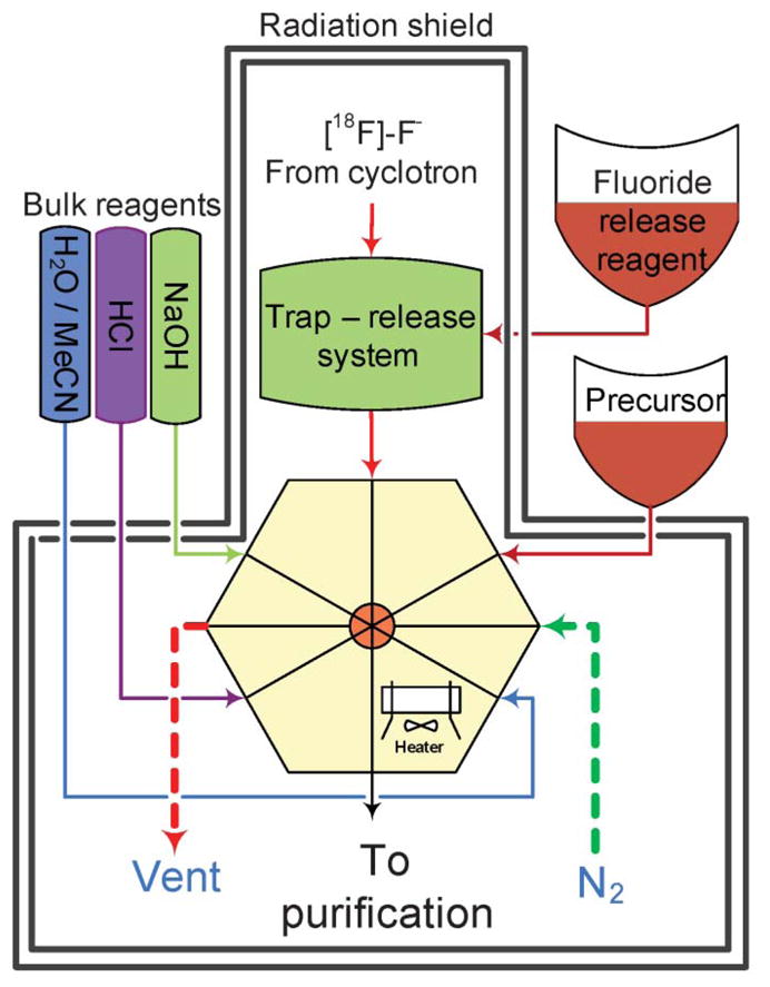
Fig. 1.

General scheme of the synthetic module. The microfluidic reactor with 8 valved ports is connected to a gas inlet, precursor delivery system, bulk reagent supply and fluoride trap-release system. The final product is transferred to a purification system.
