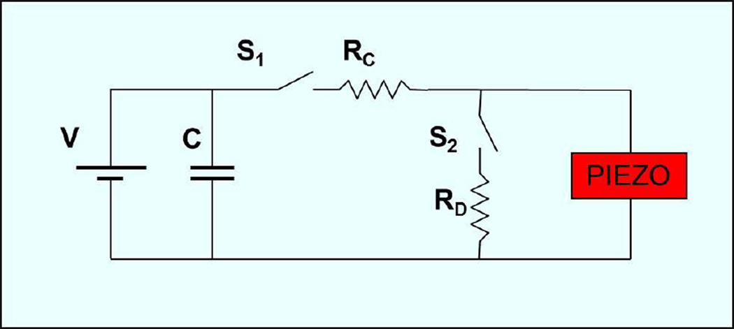
Figure 6.
Schematic of the circuit used to drive the piezoelectric actuator. V represents the power supply used to power the system and set the voltage. The power supply charges a large capacitor C that provides the instantaneous power required for actuation. S1 and S2 are synchronized switches. Rc and Rd are the resistances used to control time constants of charging and discharging respectively. Normally S1 is open and S2 is closed and therefore the piezo is at rest, upon actuation S2 is opened and S1 closed to allow charging of the piezo.

