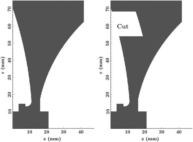
Figure 2.
Cross section diagrams of the two lenses used. On the left is the original lens used for validation of the model. On the right is the new lens with the cut, a feature of clinical interest, which exhibits a longer axial extent of the focal region. corresponds to the central axis of the lenses.

