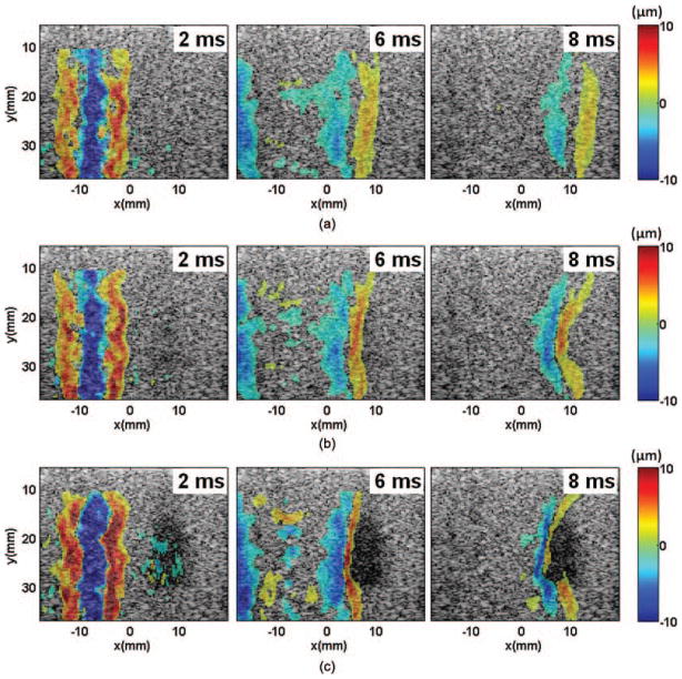
Fig. 2.
Spatial-temporal displacement images acquired at different times after the shear wave generation in the phantoms: (a) control, (b) 100 pulses, and (c) 1000 pulses. The positive and negative displacements indicate directions of motions toward and away from the imaging probe, respectively. The shear waves were generated in the left part of the field of view, centered at around x = −8 mm, and propagated away from the push region in opposite directions. The shear waves propagated at a lower speed in the lesion area, resulting in a bent wavefront as shown in panels (b) and (c). The curvature increased with increasing numbers of therapy pulses. The shear waves could not propagate far into the lesions created with more than 1000 pulses/location.

