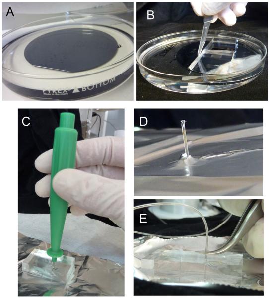
Figure 5.
Making of the PDMS block. (A) The template from Figure 4 is placed in a petri dish and covered by a ~5mm thick PDMS that is cross-linked. A piece of PDMS is cut out (B) to be punched holes at the inlets and outlets (C). The hole has to be drilled all the way and the PDMS piece that enters the puncher's bore must be removed before retrieving the puncher (D). (E) Insertion of the tubing. The tubes must be inserted only to ~1/3 of the height of the PDMS to avoid excessive strain at the inlet and outlets (which leads to leakage).

