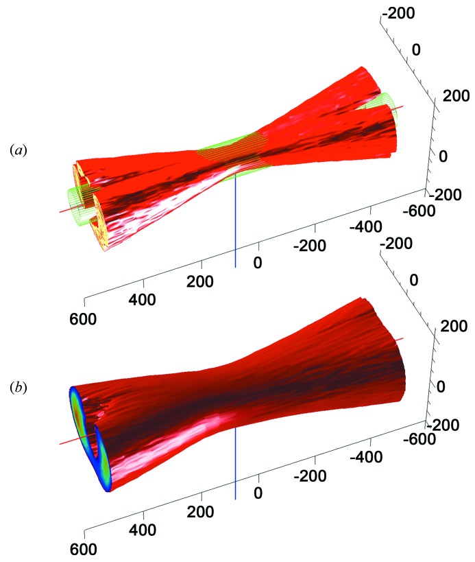
Figure 4.
Three-dimensional reconstruction of beam profiles of (a) the excitation branch of the MS2 (coupling via 100 µm fiber) and (b) the collection branch (coupling via 400 µm fiber). Illumination intensities were measured on a CCD detector array mounted perpendicular to the X-ray axis. Intensity images were recorded every 50 µm in the range from 0.5 mm upstream to 0.5 mm downstream of the sample position, and the illumination volume was reconstructed using MATLAB. The red line shows the X-ray axis with the green mesh depicting the approximate size of the X-ray beam (100 µm); the blue line marks the sample position. Left is downstream and right upstream. Beam sizes depicted here are identical to the configuration shown in Fig. 3 ▶. From these mappings the sample volumes with full overlap of X-ray and spectroscopic beams can be determined.

