Fig. 9.
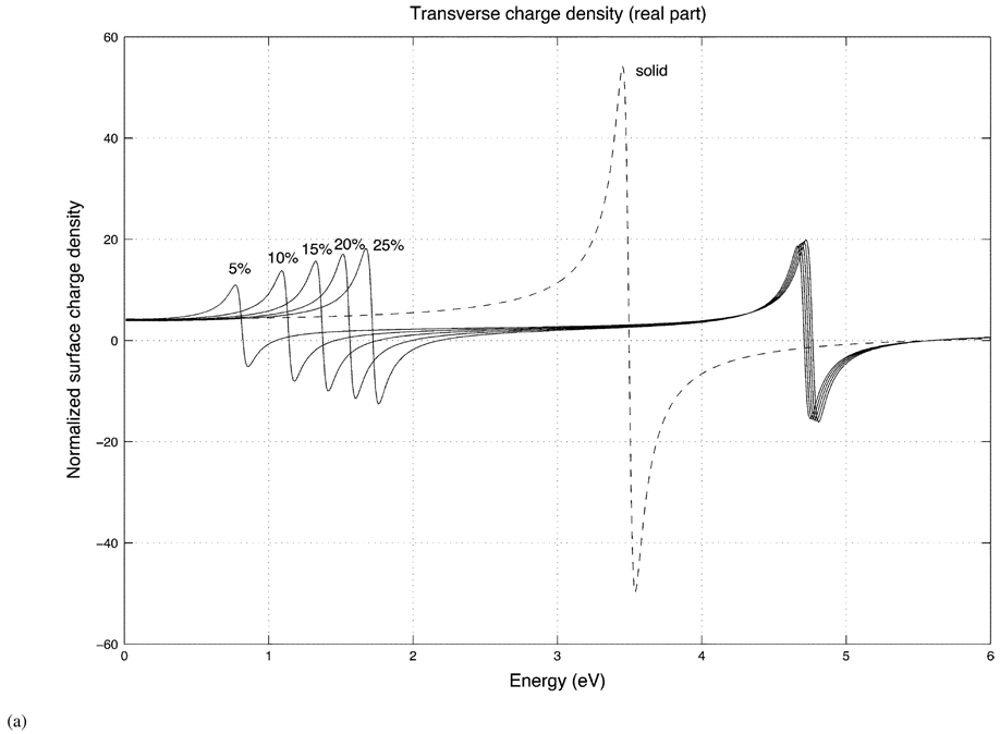
(a) Real part of the surface charge density for oblate shells of differing shell thicknesses (5%, 10%, 15%, 20%, 25%) with a fixed aspect ratio (2 to 1) for a transversely incident field. The dashed curve is the charge density of the solid oblate spheroid. In each case, the charge density is evaluated on the equatorial edge (ϑ = 90°) of the shell.
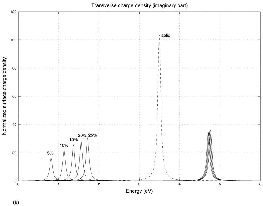
(b) Imaginary part of the oblate transverse response for different shell thicknesses.


