Abstract
We present a method to add reagent to microfluidic droplets by enveloping them as a double emulsions in reagent-filled droplets and then rupturing them with an electric field. When the double emulsions rupture, they release their contents into the enveloping droplets, ensuring mixing with reagent while limiting cross-droplet contamination.
INTRODUCTION
Droplet-based microfluidic techniques are useful for chemical and biological applications requiring the screening of millions-to-billions of separate reactions, including combinatorial synthesis,1 directed evolution,2 single-cell analysis,3, 4 and quantitative digital PCR.5, 6 In applications like these and many others, reagents must be added to the droplets at different times. For example, in directed evolution,2 it is often necessary to add reagents to induce protein expression at one time, and additional reagents to measure the property of interest for the expressed protein at another time.
Two common methods for adding reagents to droplets are droplet coalescence3, 7, 8, 9 and picoinjection.10, 11, 12 Both employ electric fields to merge the contents of the target droplets with the reagent to be added. Because the target droplets join with the reagent while sharing the same carrier oil, it is possible for material to transfer between different target droplets. For example, in coalescence, droplets can escape merging or become partially merged only to be joined downstream. Such unsuccessful mergers can occur when combining droplets with a large size disparity or combining more than two droplets8 and are more prevalent at high flow rates where droplet contact is brief. In picoinjection, fluid from one target droplet may remain at the picoinjector and be added to a droplet that follows, also leading to some cross-contamination.12 In fact, a system with a similar geometry has even been used to mix drops.13 When performing sensitive reactions like digital PCR, capable of amplifying single molecules, even minimal cross-contamination can be detrimental.
In this paper, we present a method to add reagents to droplets that ensures mixing and is robust against cross-contamination. In contrast to droplet coalescence and picoinjection that merge the target droplets with the reagent while both are in the same carrier oil, in our method, the target droplet is enveloped within a droplet of the reagent; the target droplet is then ruptured using an electric field, releasing its contents into the reagent droplet. Because the target droplet is entirely enveloped within the reagent droplet when it ruptures, all of its contents are contained in the reagent droplet, preventing cross-contamination between different target droplets. Just as with droplet merger and picoinjection, our approach is robust and simple to implement and allows different volumes of target and reagent fluid to be combined in the final droplet.
MATERIALS AND METHODS
Our microfluidic devices are constructed using conventional poly(dimethylsiloxane) (PDMS) fabrication techniques.14 First, we construct a master by spinning layers of SU-8 photoresist onto a 3-inch silicon wafer and sequentially exposing the layers to ultraviolet light (Blakray) patterned with a mylar mask (Fineline Imaging). After developing in propylene glycol monomethyl ether acetate (PGMEA), the master is covered in PDMS (Sylgard 184 Elastomer Kit) using a 10:1 polymer to cross-linker mixture ratio, placed in vacuum to remove trapped air bubbles, and baked for 1 h at 75 °C. The device is then peeled from the master and punched with access holes using a 0.75 mm biopsy coring needle. The device is bonded to a 1 mm-thick glass slide by exposing both to 1 mbar O2 in a 300 W plasma cleaner for 20 s, sealing the two exposed surfaces, and baking for 10 min at 75 °C.
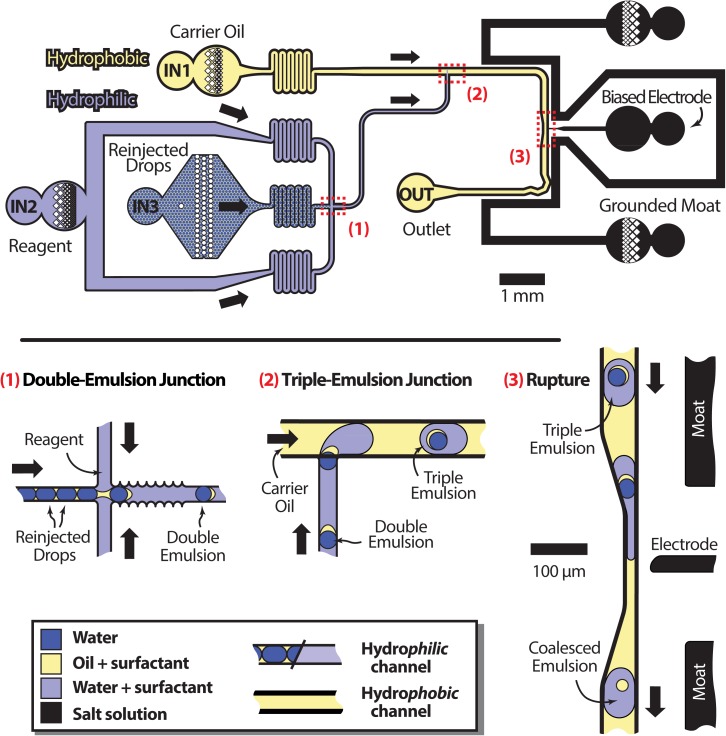
To enable the formation of double emulsions and their subsequent encapsulation in triple emulsions, we require a microfluidic device with spatially patterned wettability. Our device (Fig 1, top) consists of a cross-junction and T-junction droplet maker in series. The cross-junction droplet maker, (1) in the figure, must be hydrophilic to form the requisite water-in-oil-in-water double emulsions, and the T-junction (2) hydrophobic to encapsulate the double emulsions in oil, forming triple emulsions. To achieve this wettability pattern, we flow Aquapel, a hydrophobic chemical treatment, backwards through the T-junction by injecting it into the T-junction outlet, OUT in the figure, and allowing it to exit from the carrier oil inlet IN1. Simultaneously, we pressurize the reagent inlet (IN2) to 15 psi; this fills the cross-junction with air that blocks the Aquapel from entering, so that this region is left untreated. At this point, the device is very hydrophobic in the T-junction and semi-hydrophilic in the cross-junction. To make the cross-junction very hydrophilic, as needed to form double emulsions, we use an additional plasma treatment biased to treat the cross junction but not the T-junction. We plug the T-junction outlet OUT and oil inlet IN1 with closed-end polyether ether ketone (PEEK) tubing (Resolution Systems, TPK.515-5M) and leave the inlets of the cross-junction IN2 and IN3 unplugged. We then re-exposed the device to 1 mbar O2 plasma for an additional minute. The plasma is able to treat the channels close to the open inlet ports of the cross-junction, but not the plugged ports of the T-junction. This makes the cross-junction very hydrophilic and leaves the T-junction very hydrophobic, precisely the wettability pattern needed to form the triple emulsions. Our treatment method is quick and simple to implement, but other more robust wettability patterning techniques can also be used, like the deposition of polyelectrolyte layers15 or the patterned attachment of polymers to the channel walls.16
Figure 1.
Schematic of the entire coalescence workflow with labelled inlets (top) and close-ups of key positions (bottom). At position (1), reinjected droplets are enveloped by an aqueous reagent phase in a hydrophilic channel. The resulting double emulsion travels to a hydrophobic junction at (2) where carrier oil encapsulates it to form a triple emulsion. At (3), the encapsulated double emulsion is ruptured with an electric field.
RESULTS
Our reagent addition technique works by enveloping the target droplet inside of a droplet of the reagent; the target droplet is then ruptured, releasing its contents into the reagent droplet. To envelop the target droplet in a reagent droplet, we use microfluidic triple emulsification. The aqueous target droplets are first prepared using a separate microfluidic device, which can be a simple droplet maker or more complex device, like a picoinjector, incubation line, or sorter. In our test experiments, the target droplets consist of Milli-Q water dispersed in fluorinated oil (Novec HFE 7500) stabilized by 1% w/w biocompatible fluorosurfactant17 and are 30 μm in diameter (15 pl). They are formed using a flow focus droplet maker with a 25 μm diameter nozzle and flow rates 300 μl/h for the aqueous and 600 μl/h for the oil. The droplets are collected into a 1 ml polycarbonate syringe (BD) and stored for the reagent addition step.
To add the reagent to the target droplets, the droplets are flowed at 20 μl/h into the reinjection inlet of the device (Fig. 1, top). The serpentine channel of the inlets increases flow resistance, reducing oscillations and making the device run more stably. The aqueous reagent added to the target droplets consists of 0.1% non-ionic surfactant (Pluronic F-68) in water introduced at 400 μl/h. As the target droplets flow into the cross junction and combine with the reagent, as shown in the close-up of (1) of Fig. 1, the hydrophilicity of the channels lifts the oil surrounding the target droplets from the walls; this encapsulates the target droplets in thin shells of oil, forming double emulsions. The walls of the double emulsion maker are grated in to trap pockets of aqueous phase, preventing oil from touching the walls and making the double emulsification more robust.
The double emulsions then travel to the T-junction, where the channels become hydrophobic and additional oil is introduced at 400 μl/h, as shown in the close-up of (2) in Fig. 1. The hydrophobicity of the channels in this region causes the reagent to lift from the walls and be encapsulated in the newly added oil, encapsulating the double emulsions too. This produces triple emulsions, composed of the original single emulsions, encapsulated in shells of oil, encapsulated in aqueous reagent droplets surrounded by oil. The volume-ratio of the reagent and target fluids and the sizes of the final droplets can be adjusted by varying the flow rates in the first and second junctions.
To complete the reagent addition process, the inner double emulsions are ruptured with an electric field, as illustrated in the close-up of (3) in Fig. 1. After rupturing, the inner droplet releases its contents into the outer reagent droplet and the oil from the shell pulls itself into a sphere. The electric field is generated by electrodes containing 3M NaCl solution, to which a ∼100 V alternating signal is applied with a fluorescent light inverter (JLK Components, BXA-12579). Another electrode (moat) is grounded, shielding other regions of the device from stray field that could unintentionally merge droplets. The droplets also pass through a small constriction when in front of the electrode, which allows the electric field to better penetrate into the triple emulsions; this allows the inner double emulsions to be controllably ruptured at lower voltages. Following rupture, the exiting droplets are as stable as any emulsion of similar size and composition, and can be thermocycled for PCR or otherwise processed.
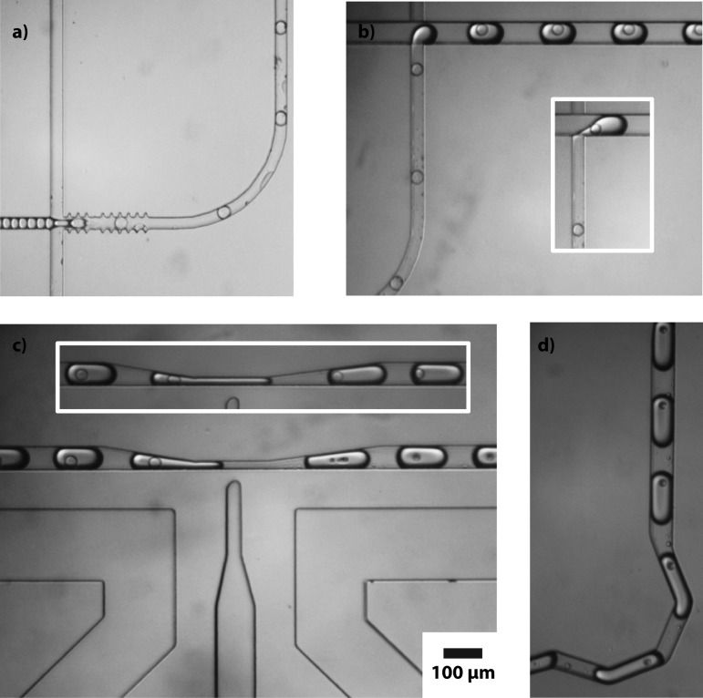
Microscope images of our microfluidic device enveloping target droplets in reagent droplets and subsequently rupturing the target droplets are provided in Fig. 2. The reinjected droplets, travelling from the left in Fig. 2a, are starkly outlined before they are encapsulated in double emulsions. This is because they consist of an aqueous phase and are surrounded by an oil phase, and the indices of refraction of these two phases mismatch. Because the droplets have curved interfaces, they act like small lenses, refracting the transmitted illumination light and appearing to have thick black edges. After the droplets are encapsulated in double emulsions, the inner and outer indices of refraction match because both phases are aqueous, and the border of the droplet becomes fainter because, even though it is oil and has a different index of refraction, the shell is very thin and unable to significantly refract the light. At the next junction, the double emulsion exits the 30 μm-square hydrophilic channel as a triple emulsion in a 60 μm-square hydrophobic channel, as seen in Fig. 2b. As with the initial target droplets, the outer edges of these triple emulsion droplets are again clearly visible, due to refractive index mismatch. The double emulsions rupture where the channel constricts to 15 μm, shown in Fig. 2c. The collapsed oil remnants are visible in the droplets and have a volume of ∼2 pl, which corresponds to oil shells that were originally ∼1 μm thick. For comparison, triple emulsions flowing through the constriction with the field switched off are shown in the inset. Without the field, no rupture occurs and, instead, the constriction causes the encapsulated double emulsions to migrate to the rear of the outer droplet. After rupture the droplets flow through a mixing module consisting of a series of zigzag channels,18 and exit the device, as demonstrated in Fig. 2d.
Figure 2.
Microscope images of the double emulsion formation (a), triple emulsion formation (b), triple emulsion coalescence (c), flipped relative to the previous figure), and the final products (d). The scale bar applies to all images.
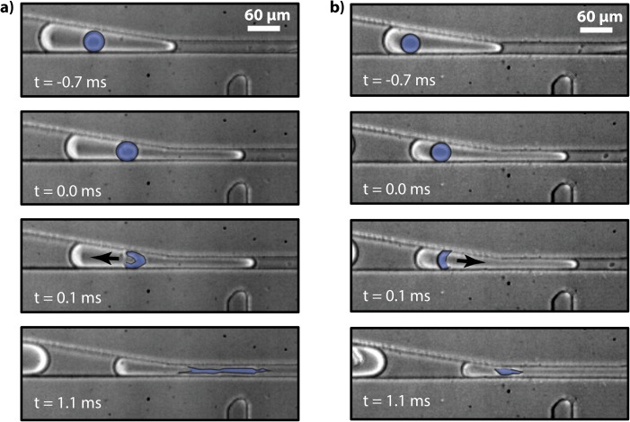
To visualize the fast dynamics of the rupture of the encapsulated double emulsions, we image the process with a high speed camera, shown in Fig. 3. In the two time series pictured, the oil shell of the double emulsion is highlighted in blue, making it easier to see. The images begin at time t =−0.7 ms, where the inner droplet is not yet squeezed in the construction and, hence, is spherical in shape. At t = 0.0 ms, the inner droplet enters the constriction and at t = 0.1 ms, it ruptures. In the image series on the left (Fig. 3a), the contents of the inner droplet are ejected towards the back of the back of the outer droplet, while in the series on the right (Fig. 3b), they are ejected to the front of the outer droplet, as indicated by the arrows. The direction of rupture appears to vary from droplet to droplet, although all double emulsions appear to rupture. After rupturing, the oil that composes the shell of the double emulsion pulls itself into a spherical droplet, as shown at t = 1.1 ms. The oil droplet remains in the outer droplet and, if desired, can be removed using techniques like droplet splitting.19 While we have used electric fields to rupture the inner droplets on the microfluidic device, they could also be ruptured off-chip using chemical additives, heat, or mechanical agitation. These methods are not compatible with on-chip rupture, but obviate the need for electrodes and electric fields, making the device simpler.
Figure 3.
Two fast-camera time series showing rupture of encapsulated double emulsions. The oil shell of the inner emulsion is false-colored blue to make it easier to see.
CONCLUSIONS
We have demonstrated that the encapsulation and controlled rupture of double emulsions is a robust method for adding reagents to a collection of droplets. Because the double emulsions are fully enveloped within the outer droplets, 100% of their contents remain within the outer droplet, making the process more robust against cross-contamination. Moreover, by incorporating passive synchronization techniques like plug-triggered droplet formation, the formation of the outer droplets can be triggered by the injection of the inner droplets, enabling every outer droplet to contain a single inner droplet. This should enable more efficient reagent addition than can be achieved with droplet merger, in which such synchronization is difficult to achieve. We anticipate our technique to be useful for applications requiring efficient, robust, and cross-contamination-free addition of reagents to droplets, including in ultrahigh-throughput droplet screening, quantitative digital PCR, and single cell analysis.1, 3, 5
ACKNOWLEDGMENTS
This work was supported by a Research Award from the California Institute for Quantitative Biosciences (QB3), the Bridging the Gap Award from the Rogers Family Foundation, the UCSF/Sandler Foundation Program for Breakthrough Biomedical Research, a grant from BASF, and the NSF through the Faculty Early Career Development (CAREER) Program (DBI-1253293).
References
- Li L., Mustafi D., Fu Q., Tereshko V., Chen D. L. L., Tice J. D., and Ismagilov R. F., Proc. Natl. Acad. Sci. U.S.A. 103, 19243 (2006). 10.1073/pnas.0607502103 [DOI] [PMC free article] [PubMed] [Google Scholar]
- Agresti J. J., Antipov E., Abate A. R., Ahn K., Rowat A. C., Baret J. C., Marquez M., Klibanov A. M., Griffiths A. D., and Weitz D. A., Proc. Natl. Acad. Sci. U.S.A. 107, 4004 (2010). 10.1073/pnas.0910781107 [DOI] [PMC free article] [PubMed] [Google Scholar]
- Brouzes E., Medkova M., Savenelli N., Marran D., Twardowski M., Hutchison J. B., Rothberg J. M., Link D. R., Perrimon N., and Samuels M. L., Proc. Natl. Acad. Sci. U.S.A. 106, 14195 (2009). 10.1073/pnas.0903542106 [DOI] [PMC free article] [PubMed] [Google Scholar]
- Zeng Y., Novak R., Shuga J., Smith M. T., and Mathies R. A., Anal. Chem. 82, 3183 (2010). 10.1021/ac902683t [DOI] [PMC free article] [PubMed] [Google Scholar]
- Beer N. R., Hindson B. J., Wheeler E. K., Hall S. B., Rose K. A., Kennedy I. M., and Colston B. W., Anal. Chem. 79, 8471 (2007). 10.1021/ac701809w [DOI] [PubMed] [Google Scholar]
- Hatch A. C., Fisher J. S., Tovar A. R., Hsieh A. T., Lin R., Pentoney S. L., Yang D. L., and Lee A. P., Lab Chip 11, 3838–3845 (2011). 10.1039/c1lc20561g [DOI] [PubMed] [Google Scholar]
- Ahn K., Agresti J., Chong H., Marquez M., and Weitz D. A., Appl. Phys. Lett. 88, 264105 (2006). 10.1063/1.2218058 [DOI] [Google Scholar]
- Mazutis L. and Griffiths D. A., Lab Chip 12, 1800 (2012). 10.1039/c2lc40121e [DOI] [PubMed] [Google Scholar]
- Priest C., Herminghaus S., and Seemann R., Appl. Phys. Lett. 89, 134101 (2006). 10.1063/1.2357039 [DOI] [Google Scholar]
- Abate A. R., Hung T., Mary P., Agresti J. J., and Weitz D. A., Proc. Natl. Acad. Sci. U.S.A. 107, 19163 (2010). 10.1073/pnas.1006888107 [DOI] [PMC free article] [PubMed] [Google Scholar]
- O'Donovan B., Eastburn D. J., and Abate A. R., Lab Chip 12, 4029 (2012). 10.1039/c2lc40693d [DOI] [PubMed] [Google Scholar]
- Eastburn D. J., Sciambi A., and Abate A. R., PLoS ONE 8, e62961 (2013). 10.1371/journal.pone.0062961 [DOI] [PMC free article] [PubMed] [Google Scholar]
- Liu Y. and Ismagilov R. F., Langmuir 25, 2854 (2009). 10.1021/la803518b [DOI] [PubMed] [Google Scholar]
- Qin D., Xia Y. N., and Whitesides G. M., Nat. Protoc. 5, 491 (2010). 10.1038/nprot.2009.234 [DOI] [PubMed] [Google Scholar]
- Bauer W. A. C., Fischlechner M., Abell C., and Huck W. T. S., Lab Chip 10, 1814 (2010). 10.1039/c004046k [DOI] [PubMed] [Google Scholar]
- Abate A. R., Thiele J., Weinhart M., and Weitz D. A., Lab Chip 10, 1774 (2010). 10.1039/c004124f [DOI] [PubMed] [Google Scholar]
- Holtze C., Rowat A. C., Agresti J. J., Hutchison J. B., Angile F. E., Schmitz C. H. J., Koster S., Duan H., Humphry K. J., Scanga R. A., Johnson J. S., Pisignano D., and Weitz D. A., Lab Chip 8, 1632 (2008). 10.1039/b806706f [DOI] [PubMed] [Google Scholar]
- Bringer M. R., Gerdts C. J., Song H., Tice J. D., and Ismagilov R. F., Philos. Trans. R. Soc. London, Ser. A 362, 1087 (2004). 10.1098/rsta.2003.1364 [DOI] [PMC free article] [PubMed] [Google Scholar]
- Link D. R., Anna S. L., Weitz D. A., and Stone H. A., Phys. Rev Lett. 92, 054503 (2004). 10.1103/PhysRevLett.92.054503 [DOI] [PubMed] [Google Scholar]


