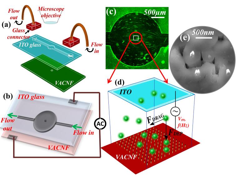
Figure 1.
Schematic of the DEP device. (a) The components of the device, including a lid electrode (indium tin oxide coated glass) with a SU layer containing a microfluidic channel, a Si chip consisting of a nanoelectrode array in a 200 μm × 200 μm area, glass fluidic connectors, and microbore tubes. (b) The electrical connections made to the device. (c) A low-magnification optical microscope image showing the flow profile of the fluorescent labeled bacteriophage solution through the circular microchamber. The stretched lines represent the length of particle movement under the hydrodynamic flow. (d) Schematic diagram of the virus particles in the active 200 μm × 200 μm NEA area, which are subjected to the hydrodynamic drag force (F Drag) in the flow direction and the dielectrophoretic force (FDEP) mostly perpendicular to the flow solution. The NEA could be fabricated with any stable metal materials and ideally in a regular array. (e) A scanning electron microscopy image of the exposed tips of carbon nanofibers which are embedded in the SiO2 matrix. The electrode tips were randomly distributed in the present study.

