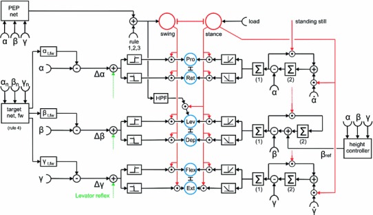
Fig. 5.

A network diagram describing a leg controller that summarizes a number of behavioral observations as detailed in the text. The right hand side depicts the sensory input relevant for stance control, the left hand side correspondingly the sensory input required for the control of the swing movement. Pairs of units depicted in blue at the center (Protractor-Retractor, Levator-Depressor, Flexor-Extensor) which are coupled via mutual inhibition (T-shaped connections), represent an abstract version of the network shown by Schumm and Cruse (2006, their Fig. 7). For definition of joint angles , and see Fig. 1. Two motivation units (swing, stance, marked in red) control the sensory input to the control network via inhibitory connections
