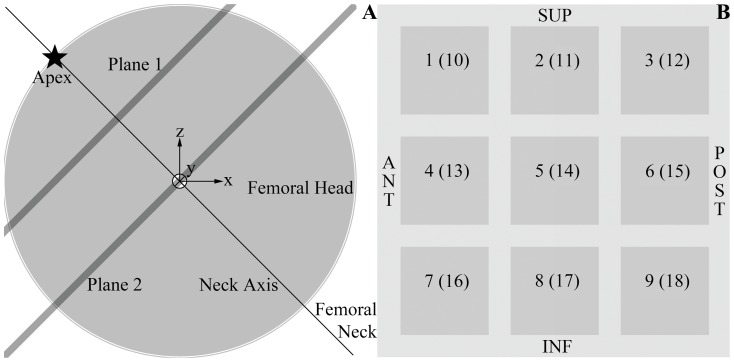
Figure 1. Spherical model of the femoral head.
(A) The femoral head was modeled as a sphere centered at the origin of a right-handed Cartesian coordinate system, and whose apex was depicted as a star in this projection of the head on an AP view. The femoral neck axis (at an angle of 135 degrees with the femoral shaft) was drawn as a thin black line going through the apex and the center of the sphere, while the planes of interest for the results shown in Figure 3 were represented as thick lines. (B) Cross-section through the femoral head showing the labeling of the different regions of the femoral head (ROIs) at two levels, planes 1 and 2 as shown in (A). ROIs 1–9 belong to plane 1 and ROIs 10–18 to plane 2.

