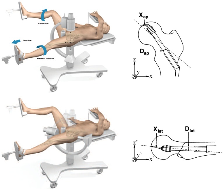
Figure 2. C-arm for AP and lateral views.
The position of the C-arm was matched to a typical view of the proximal femur with an implanted hip screw, both AP and lateral. The corresponding components of the tip-apex distance were also shown to illustrate Eq. 1. Finally, the two coordinate systems xyz and x′y′z′ were also described. The axes should actually have their origin at the center of the femoral head, but were translated to make the diagrams less cluttered. xyz are related to an AP view while x′y′z′ result from two rotations applied to xyz (see Materials and Methods section). Reproduced with permission from Stryker and Baumgaertner [3].

