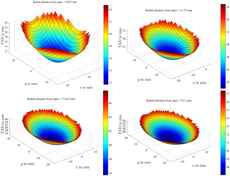
Figure 4. TAD values within a given plane.
TAD values were plotted for all the possible positions of the lag screw tip within planes whose projection on plane xz was characterized by an angle of 45 degrees with the x-axis. These planes were further defined by the radial distance which separates them from the apex of a femoral head of 47 mm in diameter. The color bars provide a visual representation of the TAD values in mm.

