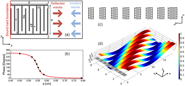
Figure 1. An acoustic metasurface for generalized Snell's law.
(a) The schematic diagram of an acoustic metasurface made of two stiff corrugated beams with a channel coiling up the space. The coiling structure has a width p = 1 cm and length a (a = 0.8 cm in this example). The width of the channel is d = 0.067p. The width of the beams is w = 0.03p, and the corrugation length is l = a − 2w − d. Sound hard boundary conditions are imposed to the left boundaries (red line) to mimic the fact that the metasurface is actually coated on a stiff plate. The light blue and dark red arrows refer to the propagation direction of incident and reflected waves, respectively. The label “1”, “2” and “3” refer to the three outlets of each element. (b) The phase of the reflected waves, as a function of the length a of the metasurface, with incident wavelength λ = 19.6p. The black dots refer to specific a values for eight units to fulfill the desired discrete phase shifts. (c) Schematic diagram of the eight units with the specific a values shown in (b) with black dots. The gap between each unit is  , with a1 and a2 denoting the length of the two adjacent coiling structures. (d) The pressure strips of the reflected waves by the eight units. The high maps of pressure field are utilized to clearly show the different phase shifts by each unit.

