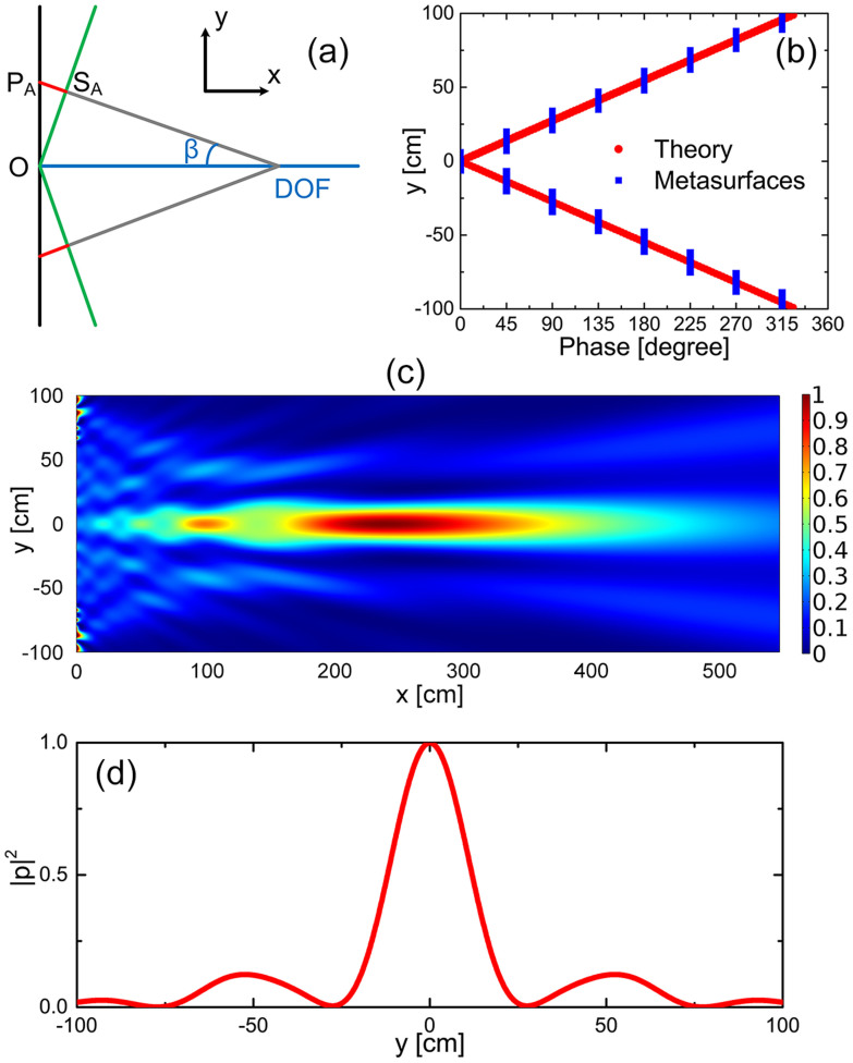
Figure 5. Acoustic axicon for the non-diffracting Bessel beam.
(a) Schematic diagram of the design of acoustic axicon. The green cone-like line with base angle  is the desired equiphase surface for the acoustic axicon so that the phase shift at
  should be proportional to the length of the red line
  . Here, the half-height of the axicon h is selected to be 100 cm. (b) The theoretical continuous phase shift (red dots) and the discrete phase shift provided by the metasurface (blue squares) along the y direction. (c) Spatial distribution of the intensity field
  for the designed axicon with
  . (d) Transverse cross-section of the intensity profile at x = 240 cm from the metasurfaces within the DOF.

