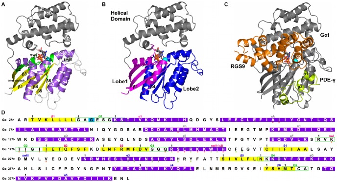
Figure 2. Structure and primary sequence of GαGTP and GαGTP-RGS-PDEγWT.
A. The cartoon representation of GαGTP structure (PDB code: 1TND) is shown. The G protein holds a Ras-like domain and an α-helical domain. The interface between α-helical and Ras-like domain makes the nucleotide binding cleft. The α-helical domain is an orthogonal bundle of six α-helices. The Ras-like domain holds a Rossmann fold, characterized by a 3-layer(αβα) sandwich architecture due to the inversion in the order of the strands β3 and β1 as well as β1 and β4, which are adjacent to each other. The Ras-like domain is colored according to secondary structure (i.e. helices, strands, and loops are, respectively, violet, yellow and white), whereas the α-helical domain is gray. The mutation site is indicated by a cyan sphere centered on the Cα-atom. The GTP nucleotide is represented by sticks colored by atoms type. The nucleotide docks into a binding site contributed by the β1/α1, α1/β2 (αF/β2 in the Gα proteins), β3/α2, β5/α4 and β6/α5 loops. These are ultraconserved regions also called G boxes 1–5 (G1–G5, colored green). G2 is also called swI (α1/β2 loop (αF/β2 loop in the Gα proteins)), whereas G3 is part of the switch II (swII, or β3/α2 loop, plus the α2-helix). The β2/β3 hairpin in between swI and swII is also called inter-switch. The β4/α3 loop, which is not a G box, is also called swIII [19]. In Gα proteins, the two domains are connected by two loops, linker 1 or α1/αA loop and linker 2 or αF/β2 loop; the latter corresponds to swI. B. According to computational experiments [20], the strands β1 and β4 divide the conserved domain into two dynamically distinct lobes, lobe 1 (i.e. the N-terminal half of the domain, colored magenta) and lobe 2 (i.e. the C-terminal half of the domain, colored blue). C. The cartoon representation of the complex involving GαGTP (gray), RGS (i.e. the RGS domain of RGS9, amino acids 286 to 418, orange), and PDEγ (green) is shown (PDB code: 1FQJ [16]). In deep detail, the RGS domain is a bundle of nine α-helices, configured into two subdomains: an N- and a C-terminal region holding an orthogonal bundle architecture (helices α1, α2, α3, α8 and α9), and a prototypical right-handed, antiparallel four-helix bundle (helices α4, α5, α6 and α7). PDEγ (residues 46–87) comprises three short α-helices and an N-terminal loop region that originates near the C-terminus and winds over helices α1 and α2. D. The primary sequence of Gα is shown. Helices, strands, and loops are, respectively, violet, yellow, and white. The G boxes are delimited by green boxes. Black numbers on the left side of the alignment refer to the sequential numbering, whereas black numbers above the sequences indicate the beginning of a secondary structure/G-box motif. An arbitrary numbering of each residue was set, characterized by the label of the secondary structure segment followed by the amino acid position within the segment. In those cases where the G-boxes overlap with the secondary structure segment, positions refer to the G-boxes. Orange and green stars mark, respectively, RGS and PDEγ recognition sites.

