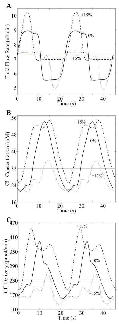
Fig. 11.
Waveforms in response to the sustained perturbations in inflow pressure of −15%, 0%, and +15% for TGF gain γ = 5 and delay τ = 3.5 s. For each perturbation, the waveforms of TAL fluid flow rate at the MD (panel A), chloride concentration at the MD (panel B), and chloride delivery rate to the MD (panel C) are in the appropriate relative phase relationship. Horizontal gray line in each panel corresponds to steady-state base-case value. Solid Curves labeled 0% in each panel represents the LCO for γ = 5 and τ = 3.5 s, for no perturbation; Dashed and dotted curves correspond to sustained perturbations of +15% and −15%, respectively.

