
Figure 1.
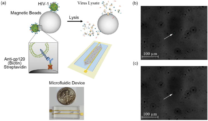
3D schematic of the electrical sensing system and fluorescent images of captured HIV-1 (a) 3D Schematic of viral capture and detection using magnetic beads conjugated with anti-gp120 antibodies (Biotin) and label-free electrical sensing of viral lysate. Streptavidin-coated magnetic beads were conjugated with anti-gp120 antibodies (Biotin). Samples were washed 4 times with 20% glycerol in grade water to remove electrically conductive DPBS. Captured viruses were then lysed using 1% Triton X-100 in grade water. The viral nano-lysate samples were used for impedance analysis by the microfluidic device with two rail electrodes. (b) Bright-field and fluorescent-field images of GFP tagged captured viruses fixed with 4% paraformaldehyde attached to magnetic beads were superimposed. White arrow points out the GFP tagged HIV-1 captured on a magnetic bead. (c) Corresponding bright-field image of the captured and fixed GFP tagged HIV-1 on the magnetic beads shown in Figure 1b. White arrow points out the corresponding magnetic bead shown in Figure 1b in bright-field.