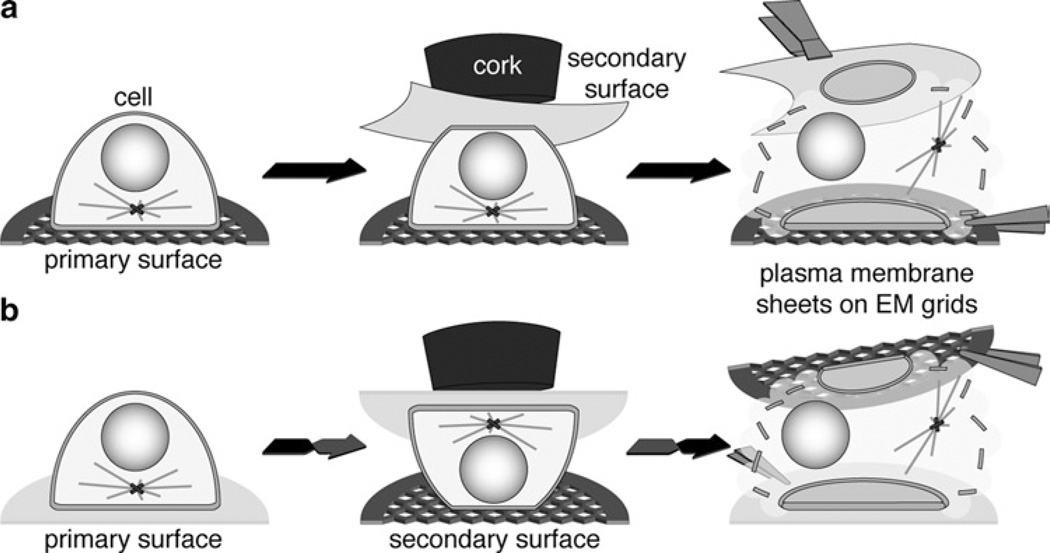
Fig. 2.
Simplified three-step illustrations of the “ripping” procedures to obtain plasma membrane sheets. (For simplification, working surface, filter papers and acetate disks are not included in the illustration.) (a) Example for the generation of plasma membrane sheets from the adherent cell side attached to a coated EM grid (primary surface). A PVDF membrane is used as secondary surface. (b) Example for the generation of plasma membrane sheets from the solvent exposed cell side attached to a PLL-coated EM grid (secondary surface). A PLL-coated cover glass is used as primary surface.

