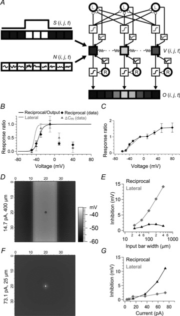
Figure 7. A model of an electrically coupled array of Mb1 bipolar cell (BC) terminals.

A, simplified diagram of the model (see Methods). Only three or nine BC units in the model array are illustrated for clarity. The visual signal S(i, j, t) and intrinsic noise N(i, j, t) charges the membrane potential of electrically coupled BC units V(i, j, t), which drives reciprocal (R) and lateral (L) inhibition through a Hill function and an alpha function for each to regulate V(i, j, t). The BC output O(i, j, t) is determined by a Hill function of V(i, j, t). In the lateral inhibitory pathway, the supralinear integration of weak inputs and the requirement of population inputs are implemented by a low voltage-dependent Hill function (grey) and by spatial summation of exponentially weighted BC inputs (λ = 100 μm), respectively. B, Hill functions for reciprocal (black) and lateral inhibition (grey) used in the model. The Hill function for reciprocal inhibition and BC output was determined to satisfy the voltage dependence of reciprocal inhibition (black diamond) and ΔCm (grey triangle) shown in Fig. 1B. The Hill function for lateral inhibition was determined to satisfy the voltage dependence of lateral inhibition as shown in C. C, the voltage dependence of lateral inhibition of the model (grey). Two neighbouring BC units at the central region of the model array were voltage clamped. Depolarization of one BC unit from −70 to −10 mV for 200 ms evoked lateral IPSP in the other voltage clamped at −90 mV. The lateral IPSP was integrated for 400 ms from the pulse onset and plotted against the membrane potentials (grey), which satisfied the experimental data in Fig. 3C (black diamond). The IPSP was normalized to the value at −10 mV. D, the output voltage profile of BC units in response to a bar input (14.7 pA in intensity, 400 μm in width) at 250 ms after the input onset. A hyperpolarizing current was injected into the BC unit at the black square (Vm: ∼−55 mV) as in Fig. 6C and D. E, effects of input bar width. Inputs with various bar widths were applied to the model as in D (14.7 pA in intensity). Reciprocal IPSP (black) and lateral IPSP (grey) in the black square region shown in D are shown. F, the output voltage profile of BC units in response to a local input (73.1 pA in intensity, 25 μm in width) applied to a single BC unit (black) at 250 ms after the input onset. A hyperpolarizing current was injected to the BC unit (Vm: ∼−55 mV) as in Fig. 6E and F. G, effects of local input intensity. Local input of various intensities was applied as in F. Reciprocal IPSP (black) and lateral IPSP (grey) in the black square region shown in F are shown. In this figure, the intrinsic noise is excluded for clarity.
