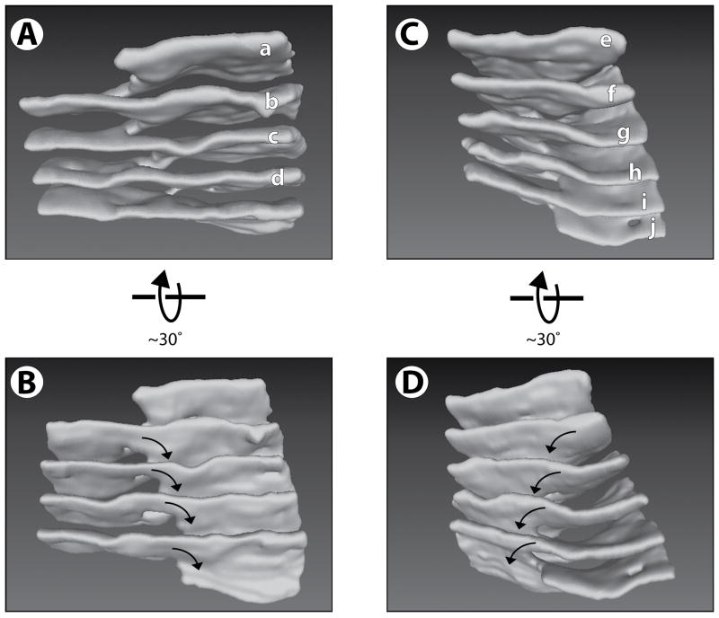
Figure 4. Structure of helical ramps connecting stacked ER sheets.
(A) A 3D reconstruction of the region within the black rectangle of Figure 3A. The sheets are labeled as in Figure 3A (left column). Movie S4 shows a Quicktime movie of this reconstruction being rotated.
(B) As in (A), but from a different view angle. The arrows indicate the handedness of the helical edge.
(C) A 3D reconstruction of the region within the white rectangle of Figure 3A. The sheets are labeled as in Figure 3A (right two columns). Movie S5 shows a Quicktime movie of this reconstruction being rotated.
(D) As in (C), but from a different view angle. The arrows indicate the handedness of the helical edge, which is opposite to that in (A) and (B). See also Figure S3.

