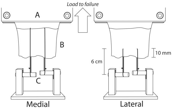
Figure 1.
Schematic diagram illustrating suture placement for tendon suture retention testing. Sutures trisected the tendon width and were placed at either the musculotendinous junction for medial tendon testing (left picture) or 10mm from the free tendon margin for lateral region testing (right picture). The cryoclamp was attached in series to a 1000N load cell and crosshead of the materials testing system (not shown). A: base of cryoclamp, B: tendon, C: adjustable bars for each suture

