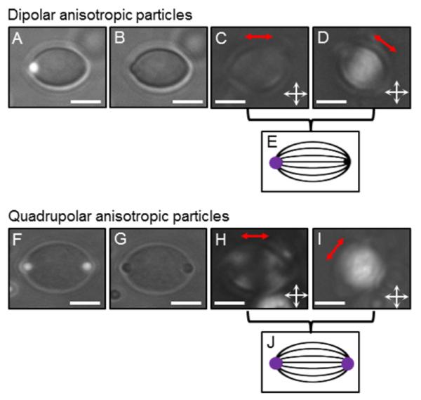
Figure 4.

Typical dipolar (A-E) and quadrupolar (F-J) anisotropic particles synthesized using methods reported in this paper. The images were acquired in water, after extraction of 5CB. (A, F) are combined Fluo and BF micrographs, (B, G) are BF micrographs, and (C, D, H, I) are PL micrographs (the red double arrows indicate the particle long axis). Scale bars: 5 μm. (E) and (J) are schematics illustrating the average orientation of the optical axis of the polymer chains (black lines) within the anisotropic particles, as deduced from the PL pictures (C, D) and (H, I), respectively. The purple spots represent the PS colloids.
