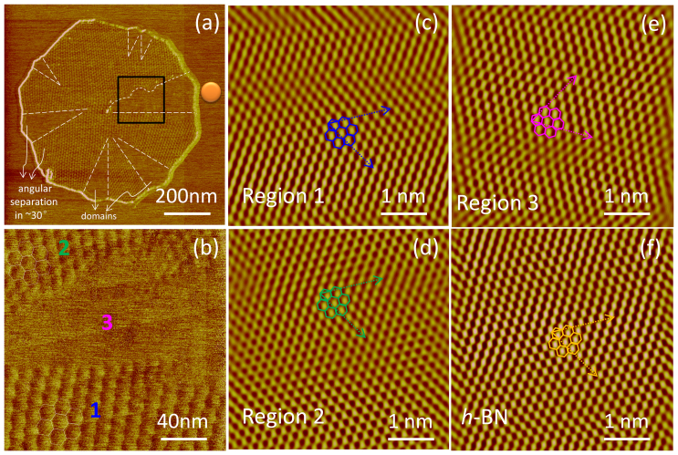
Figure 3. Friction imaging of polycrystalline monolayer graphene on h-BN.
(a) A typical polycrystalline graphene grown on h-BN. The graphene flake with giant moiré patterns is stitched with several domains where the moiré pattern is invisible. Dashed lines depict the shapes of the “blank” regions. The blank regions seem radiated from the center of the graphene flake; (b) Magnified friction images from the black box in panel (a). The moiré patterns exhibit discontinuity. Regular hexagons demonstrate the lattice of moiré pattern; (c), (d), (e) and (f) are the atomic scans (5 × 5 nm2) taken from the blue, pink, green and orange positions in panel (a) and (b), regular hexagons demonstrate the lattice of graphene and h-BN, respectively. Zigzag directions (in dashed line) and lattice vectors (in solid line) are indicated by arrows. The atomic images are filtered to improve clarity. Above images are measured with the same scan angle. In region “1” and “2”, their moiré patterns have a 12° angular difference although the graphene lattice in both regions seems to follow that in h-BN substrate pretty well. The graphene lattice in region “3” is rotated of about 30° with respect to the h-BN lattice. The corresponding unfiltered raw images of (c–f) are shown in Fig. S7.

