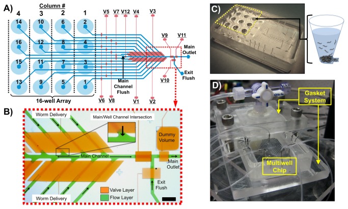
Figure 1. Population Delivery Chip design.
A) A schematic of the device indicating the flow layer (blue) and control valve layer (red). There are 16 on-chip wells arranged in a 96-well plate format for initial loading of different worm populations. Columns and wells of the array are numbered according to order of delivery. Valves V1-V8 are multiplexer control valves and V9-V12 control flow in the main channel. B) An image of the device with its microfluidic channels loaded with food coloring dye, showing the flow layer (green) and control valve layer (orange) (scale bar ~1mm). C) A macro-scale view of the device with the 16-well array indicated by the yellow dashed lines and a schematic of worms loaded into one of the conical wells. D) A macro-scale view of the entire chip/gasket system with pressurized input lines in the experimental setup.

