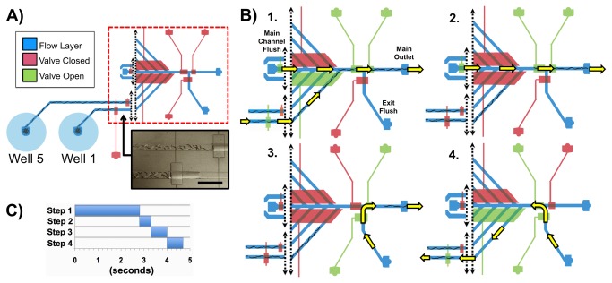
Figure 2. Automated worm population delivery sequence.
A) Schematic of the device showing areas active during the sequence example as the worms are pre-staged at the first set of control valves. An image of pre-staged C. elegans worms is below the schematic (scale bar is 1 mm). B) Illustration of all steps for one full sequence cycle. Step 1: Appropriate valves open as the gasket is pressurized to send Well 1’s population to the main channel, where Main Channel Flush then accelerates the worms’ transport to the main exit. Step 2: Excess worms are cleared from the main channel towards the Main Outlet via flow from Main Channel Flush. Step 3: Flow from Exit Flush delivers the worms from the Main Outlet to an off-chip location. Step 4: “Flushback”; Exit Flush flow is redirected backwards to clear any remaining worms in the well channel back to Well 1. This step is executed on Wells 1-4 only after finishing Steps 1-3 on each of them. C) Timings for each step.

