
Figure 10.
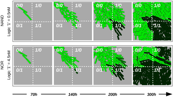
Multi-functional behaviour of the circuit. Spatial cell growth simulation shown, where the inputs are embedded in the surface as follows: top-left quadrant has no inputs, top-right quadrant has input A (1-0), bottom-left has only input B (0-1) and bottom-right has both inputs A and B (1-1). Both rows show the expression of Out over time, but for different logic “1” standards: 4.5 nM for a NOR logic function (top) and 0.5 nM for a NAND logic gate (bottom). Logic “0” is 0.0 nM in all simulations. a.u.: arbitrary units. Generation time of cells = 24h.