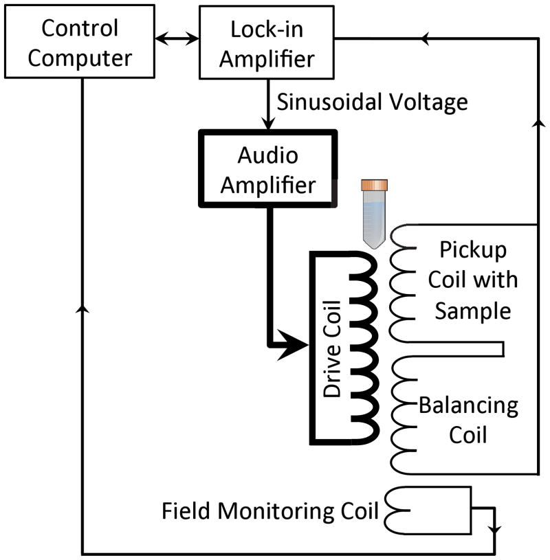
Figure 2.
Diagram of the apparatus used to measure the MSB signals from samples of magnetic nanoparticles. The pickup coil and balancing coil were fixed inside the drive coil producing the applied field. The pickup and balancing coils were connected in series and the output was measured using the phase-lock amplifier. The computer controlled the phase-lock amplifier and the switched capacitors, which together determined the drive field amplitude and frequency. The computer also recorded the phase-lock amplifier measurements of the third and the fifth harmonics. The ADC card in the computer sampled the drive field as the phase-lock amplifier sampled the harmonics to maintain the field at the desired amplitude.

