
Figure 3. Arrangement of the outer COPII coat.
(A) Visualization of the positions and orientations at which vertices were identified for a representative tube. They are arranged to form a rhomboidal lattice. The positions of inner coat subunits are shown in grey (Figure 4). (B) Visualization of the positions of aligned rods, as in panel A. Right- and left-handed rods in purple and green respectively. (C) Schematic depiction of how ‘+/−’ rods can coat regions of spherical curvature by arranging to form orthogonal vertices (left panel). Tubular surfaces (right panel) are coated with +/+ and −/− rods that form parallel vertices (alpha and beta are always in the same direction with respect to the tube axis).

Figure 3—figure supplement 1. Current models for assembly and size variation of outer COPII coat cages.
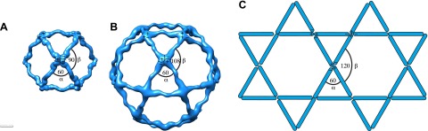
(A) The 60 nm cuboctahedral cage is formed by twofold symmetrical vertices linked by rods. The angle alpha is 60°, the angle beta is 90° (see Figure 2—figure supplement 2A for definition of alpha and beta) (Stagg et al., 2006). (B) In the 90 nm icosidodecahedral cage (Stagg et al., 2008), alpha is 60°, but beta is 108°, leading to formation of pentagonal faces. (C) If beta was sufficiently flexible to form 120° angles, hexagonal faces could form, leading to assembly of a flat coat, as hypothesized by Stagg et al. (2008). Combinations of square, pentagonal and hexagonal faces into the same cage could potentially increase the extent of size variations allowed for the COPII coat.
Figure 3—figure supplement 2. Variability and flexibility in the outer coat calculated from the coordinates of aligned subtomograms.

Note that the variability around the mean values may result from alignment errors from the subtomogram averaging. (A) The distances between neighbouring vertices measured along right-handed +/+ rods (purple), and along left-handed (−/−) rods (green). (B) Alpha and beta angles measured based on the coordinates of each vertex and the two corresponding neighbouring vertices. (C) A rhomboidal lattice could take two forms. In the first, each vertex would have the same orientation relative to the tube (left-hand panel). In this case the alpha and beta angles would always have the same orientation relative to the direction of the tube, and alpha could be smaller than beta. In the second, each vertex would be rotated by approximately 90° in the plane of the membrane relative to the adjacent vertices (right-hand panel). In this second form, alpha and beta would both be close to 90°. Assembling the second form would therefore require more substantial deformation of the vertex structure seen in in vitro assembled cages, in which alpha is smaller than beta.
Figure 3—figure supplement 3. The unit cell dimensions for the inner and outer coat lattices.

The unit cell angles for the inner coat lattice are 83.8° ± 10° and 95.4° ± 9.8°, very close to the angles of 79.7° ± 5.9° (alpha) and 95.7° ± 5.8° (beta) measured for the outer coat. The distance between neighbouring outer coat vertices in the right-handed direction (30.2 ± 2 nm) is similar to the distance between two rows of inner coat subunits (30.2 ± 2 nm), while the distance between outer coat vertices in the left-handed direction (31.9 ± 1.9 nm) is similar to the distance between 4 inner coat subunits (31.4 ± 4.5 nm). The two lattices are therefore very closely matched.