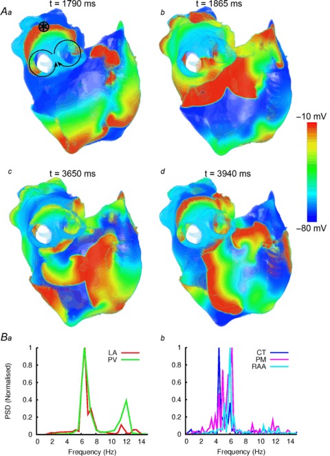
Figure 9. Simulated AF induced by rapid pacing.

A, snapshots of wave propagation at various timings (a–d), illustrating the development of a re-entrant circuit around the RPV (a, b) and the development and breakdown of re-entry in the RA (c, d). The distribution of the membrane potential in the 3D atrial tissue is shown using a standard rainbow palette. Circle with an asterisk indicates the stimulation site. B, dominant frequency analysis of locations within the LA (a) and RA (b).
