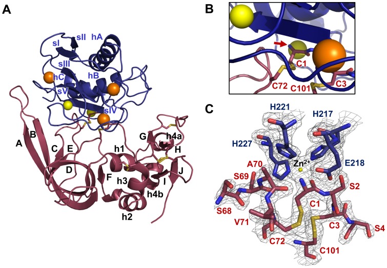
Figure 1. Crystal structure of MMP-10cd/TIMP-2 complex.
(A) Structural overview of the complex shows the MMP-10cd in blue, zinc ions in yellow, calcium ions in orange, disulfide bridges in gold, and TIMP-2 in raspberry. The N-terminal domain of TIMP-2 is positioned to the left, comprising β-strands A–F, helices 1–3 and intervening loops, and the C-terminal domain is positioned on the right, comprising β-strands G–J, helices 4a and 4b, and connecting loops. Numbering shown is consistent with early descriptions of TIMP-1 and TIMP-2 structures from the Bode group [26], [27]; helix 4a within the multiple turn loop was originally not numbered. (B) A closer view of the cartoon structure in the vicinity of the active site shows the TIMP-2 N-terminal residue Cys-1 (red arrow) coordinated to the catalytic zinc ion directly behind. (C) The 2Fo-Fc electron density map contoured at 2.0σ around the MMP-10cd active site shows the catalytic zinc coordinated by side chains of His-217, Glu-218, His-221, and His-227. The bound molecule of TIMP-2 also coordinates the catalytic zinc via the terminal amine and carbonyl oxygen of Cys-1. Numbers shown in blue correspond to MMP-10 residues and numbers in red to TIMP-2 residues.

