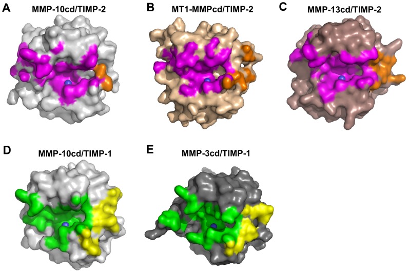
Figure 6. Diversity of MMP contact surfaces interacting with TIMP N- and C-terminal domains.
MMPs are shown in the standard frontal orientation, with catalytic zinc shown as a blue sphere. (A) MMP-10cd/TIMP-2: MMP-10cd surface is shown in grey with footprint of the surface buried by TIMP-2 N-terminal domain in magenta and C-terminal domain in orange. (B) MT1-MMPcd/TIMP-2 (PDB ID: 1BQQ) [27]: MT1-MMPcd surface is shown in wheat with footprint of the surface buried by TIMP-2 N-terminal domain in magenta and C-terminal domain in orange. (C) MMP-13cd/TIMP-2 (PDB ID: 2E2D) [28]: MMP-13cd surface is shown in brown with footprint of the surface buried by TIMP-2 N-terminal domain in magenta and C-terminal domain in orange. (D) MMP-10cd/TIMP-1 (PDB ID: 3V96) [24]: MMP-10cd surface is shown in grey with footprint of the surface buried by TIMP-1 N-terminal domain in green and C-terminal domain in yellow. (E) MMP-3cd/TIMP-1 (PDB ID: 1UEA) [26]: MMP-3cd surface is shown in dark grey with footprint of the surface buried by TIMP-1 N-terminal domain in green and C-terminal domain in yellow. The MMP contact surfaces shown are for atoms within 4.5 Å of the TIMP; figures were generated using PYMOL.

