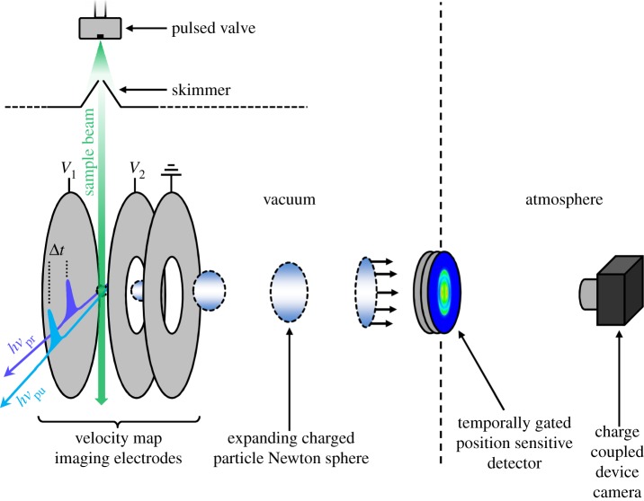
Figure 3.
Schematic of a velocity map imaging arrangement used to perform TR-MS, TR-VMI or TR-PES experiments. V 1 and V 2 correspond to the voltages applied to the repeller and accelerator electrodes, respectively. For VMI, the voltage ratio V 1:V 2 is set to approximately 1:0.7. Further information regarding each technique is provided in §2.

