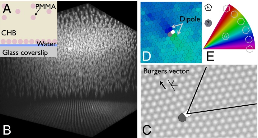
Fig. 1.
Lattice used in the experiments presented here. (A) Charged PMMA particles in CHB/dodecane are bound, by image charge attraction, to an oil–water interface formed on a glass coverslip. (B) Confocal image of a sample cell shows the lattice on the interface with a few dislocations frozen in by the fabrication process. Above (displaced by a vertically applied electric field to better view the 2D lattice) is a 3D Wigner lattice of the PMMA particles in CHB/dodecane. (C) Bright-field image of a section of the lattice showing a single dislocation. The extra half-rows that give rise to the dislocation (shown in black) meet at the core, which is also characterized by a pair of particles having five and seven nearest neighbors. A dislocation will be represented interchangeably by a bound (5–7) pair of Voronoi cells (overlaid), or by a line parallel to the Burgers vector and a V along the extra half-rows. The corresponding topological charge of the dislocation, its Burgers vector, is also shown. (D) Lattice can be represented through its Voronoi cells, colored by orientation. (E) In this picture the dipole in orientation which surrounds a dislocation is clearly visible. Only cells with six nearest neighbors are colored this way. Cells with five and seven neighbors are colored white and gray, respectively.

