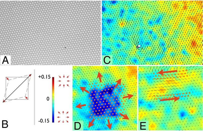
Fig. 2.
Representation of the strain field. Starting from an image of the lattice (A), the particle displacement field was determined by comparing each Voronoi cell to an ideal one. We represent the strain tensor, derived from the displacement field, as follows. (B) The isotropic (compression/dilation) part is represented with color and the shear component by a rod along the direction of the shear elongation having length proportional to the magnitude of the shear strain. (C) Visualization of the strain field of the lattice shown in A makes immediately apparent strains which are not evident from the bright-field image. The strain is a combination of long-range strains created either by boundary conditions or by defects outside the field of view and shorter-range strains induced either by local defects or the application of topological tweezers (D and E). (D) Application of an incommensurate dilated potential produces a patterned dilation (blue) strain. The patterns visible in the strain have a length scale corresponding to a beat frequency between the incommensurate potentials. (E) Application of shear stress produces a matching shear strain visible in the region in between the shearing traps.

