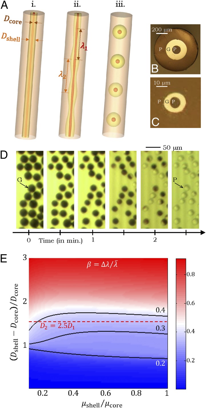
Fig. 3.
Inorganic sacrificial buffer layer to facilitate particle extraction. (A) Schematic of the fiber structure. (B and C) Optical reflection micrographs of the fiber cross-section at two stages in the fabrication process (Supporting Information). The core consists of a PES (P) cylinder surrounded by a layer of an inorganic glass, As2Se3 (G). The core is embedded in a PES cladding matrix. (D) Time-lapse transmission optical micrographs of core (P)/shell (G) particles placed in NaOH solution. The glass shell is dissolved, leaving behind the polymer cores. (E) Theoretically predicted values for the figure-of-merit  based upon calculated breakup wavelengths
  and
and  assuming equal-amplitude perturbations (Supporting Information). Black continuous lines are contours of fixed
  at the values of
  ,
,  , and
, and  . The dashed red line corresponds to the experimental values of
  and
and  . D1 and D2 are the experimental values for Dcore and Dshell, respectively.

