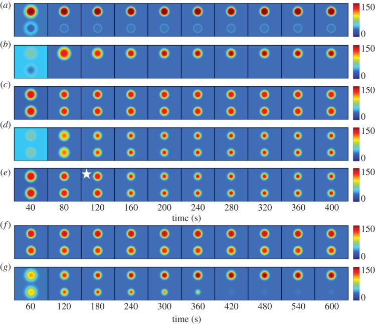
Figure 7.
Modelling polarity establishment in diploids. (a) An Rsr1–GEF patch was placed at either end of the cell, with an Rga1–GAP plug in the lower patch. Rsr1–GEF at 2.5% of Bem1–GEF. (b) Rsr1–GEF patches with an Rga1–GAP plug in the lower patch. Rsr1–GEF at only 0.025% of Bem1–GEF. (c) Rsr1–GEF patches with no Rga1–GAP plug. Rsr1–GEF at 2.5% of Bem1–GEF. (d) Rsr1–GEF patches with no Rga1–GAP plug. Rsr1–GEF at only 0.025% of Bem1–GEF. (e) Rsr1–GEF patches with no Rga1–GAP plug. Rsr1–GEF at 2.5% of Bem1–GEF but Rsr1–GEF was turned off at 120 s (indicated by star). (f) Uneven Rsr1–GEF patches (55 : 45 ratio), with no Rga1–GAP. Rsr1–GEF at 2.5% of Bem1–GEF. (g) Uneven Rsr1–GEF patches (55 : 45 ratio), with no Rga1–GAP. Rsr1–GEF at only 0.025% of Bem1–GEF.

